Chrysler Pacifica. Manual - part 422
(14) Check and adjust brake fluid level as neces-
sary.
(15) Perform wheel alignment. (Refer to 2 - SUS-
PENSION/WHEEL
ALIGNMENT
-
STANDARD
PROCEDURE)
KNUCKLE
DESCRIPTION
The steering knuckle is a single aluminum cast-
ing with legs machined for attachment of the strut
assembly,
steering
linkage,
disc
brake
caliper
adapter, lower control arm ball joint and steering
linkage. The hub and bearing assembly is mounted
in the center of the steering knuckle using 4 bolts.
The driveshaft’s constant velocity (C/V) stub shaft is
splined through the center of the hub and bearing
and is held in place using a nut, nut lock and cotter
pin.
Service replacement of the front hub and bearing
assembly can be done with the steering knuckle
remaining on the vehicle.
REMOVAL
(1) Raise and support vehicle. (Refer to LUBRICA-
TION & MAINTENANCE/HOISTING - STANDARD
PROCEDURE)
(2) Remove wheel and tire assembly.
(3) Remove cotter pin, nut lock and spring washer
from end of halfshaft stub shaft and hub nut (Fig. 1).
(4) With aid of a helper applying brakes to keep
front hub from turning, remove hub nut (Fig. 1).
(5) Access and remove front brake rotor. (Refer to
5 - BRAKES/HYDRAULIC/MECHANICAL/ROTOR -
REMOVAL)
(6) Disconnect vehicle wiring harness from wheel
speed sensor connector (Fig. 2).
(7) Unclip wheel speed sensor connector and rout-
ing clip from frame rail outer reinforcement (Fig. 2).
(8) Remove screw fastening wheel speed sensor
routing bracket to strut assembly (Fig. 3).
(9) Open routing clip at knuckle and remove wheel
speed sensor cable (Fig. 4).
(10) Push in on end of halfshaft stub shaft, push-
ing its splines out of hub splines.
(11) Remove nut attaching outer tie rod to steering
knuckle (Fig. 7) by holding outer tie rod stud station-
ary while loosening and removing nut with a wrench.
(12) Remove tie rod from steering knuckle using
Remover, Special Tool C-3894-A (Fig. 8).
(13) Remove two bolts attaching strut clevis to
steering knuckle (Fig. 9) (Fig. 10).
(14) Tip knuckle outward at top and remove half-
shaft stub shaft from hub and bearing. Suspend
driveshaft straight outward using a bungee cord or
wire. Do not allow driveshaft to hang by inner
joint.
(15) Remove ball joint nut using a power impact
wrench. Because tapered stud is held suffi-
ciently in knuckle at this time, it is not neces-
sary to hold stud stationary to remove nut.
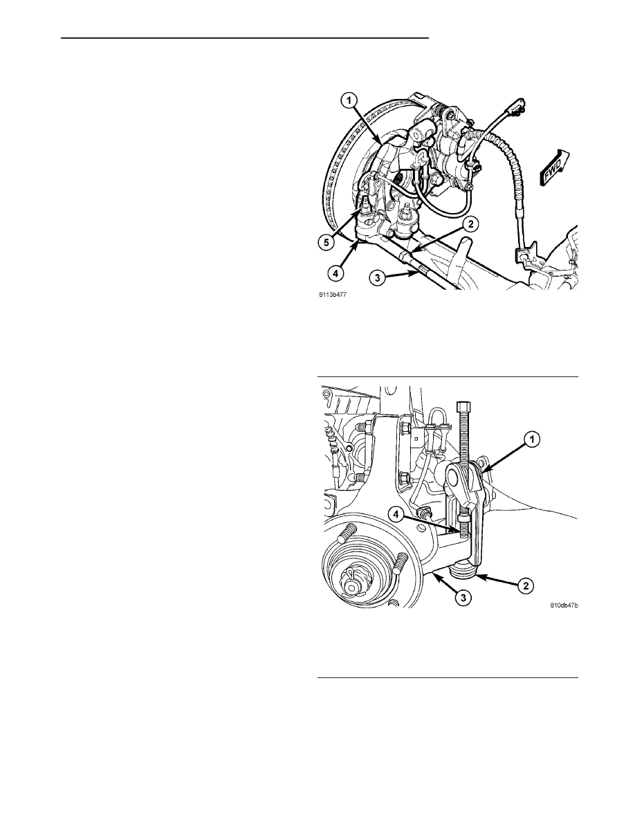
Fig. 7 Tie Rod Attachment
1 - STEERING KNUCKLE
2 - JAM NUT (TIE ROD ADJUSTMENT)
3 - INNER TIE ROD SERRATIONS
4 - OUTER TIE ROD
5 - NUT
Fig. 8 Using C-3894-A To Release Tie Rod
1 - PULLER C-3894-A
2 - OUTER TIE ROD
3 - STEERING KNUCKLE
4 - TIE ROD STUD
CS
FRONT SUSPENSION
2 - 5
HUB / BEARING (Continued)