Chrysler Stratus Convertible. Manual - part 372
INTAKE MANIFOLD—LOWER
REMOVAL
(1) Disconnect
negative
cable
from
auxiliary
jumper terminal (Fig. 44).
WARNING: RELEASE FUEL SYSTEM PRESSURE
BEFORE SERVICING FUEL SYSTEM COMPONENTS.
SERVICE VEHICLES IN WELL VENTILATED AREAS
AND AVOID IGNITION SOURCES. NEVER SMOKE
WHILE SERVICING THE VEHICLE.
(2) Release fuel system pressure. Refer to Group
14, Fuel System for procedure.
WARNING: WRAP SHOP TOWELS AROUND HOSE
TO CATCH ANY GASOLINE SPILLAGE.
(3) Disconnect fuel supply tube from rail. Refer to
Group 14, Fuel System for procedure.
(4) Remove upper intake manifold. Refer to proce-
dure in this section.
(5) Disconnect electrical connectors from fuel injec-
tors.
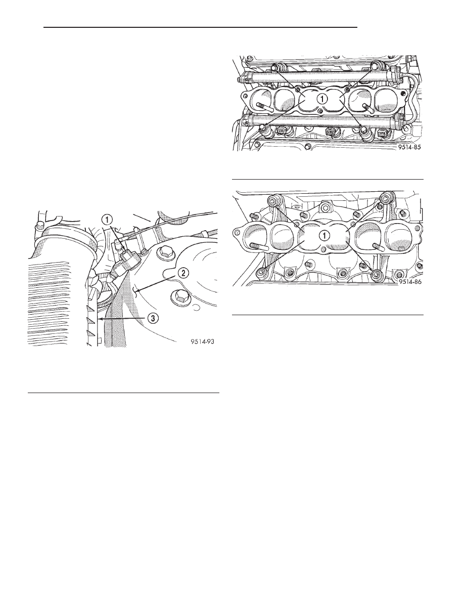
(6) Remove bolts holding fuel rail (Fig. 45).
(7) Lift fuel rail off engine. There are spacers
under each fuel rail bolt (Fig. 46).
(8) Remove lower intake manifold attaching bolts.
Remove intake manifold (Fig. 47).
INSTALLATION
(1) Install new intake manifold gaskets (Fig. 47).
(2) Install intake manifold, spring washers and
nuts (Fig. 47).
(3) Tighten the intake manifold mounting nuts
(Fig. 48) one bank after the other by using the fol-
lowing procedures:
• Tighten nuts “R” to 6.4 N·m (56 in. lbs.)
• Tighten nuts “L” to 21 N·m (185 in. lbs.)
• Tighten nuts “R” to 21 N·m (185 in. lbs.)
• Tighten nuts “L” again to 21 N·m (185 in. lbs.)
• Tighten nuts “R” again to 21 N·m (185 in. lbs.)
(4) Apply a light coating of clean engine oil to the
O-ring on the nozzle end of each injector.
(5) Insert fuel injector nozzles into openings in
intake manifold. Seat the injectors in place. Tighten
fuel rail bolts to 12 N·m (8 ft. lbs.).
(6) Attach electrical connectors to fuel injectors.
(7) Connect fuel supply tube to fuel rail. Refer to
Group 14, Fuel System for procedure.
(8) Install upper intake manifold. Refer to proce-
dure in this section.
(9) Connect negative cable to auxiliary jumper ter-
minal.
Fig. 44 Auxiliary Jumper Terminal
1 – AUXILIARY JUMPER TERMINAL
2 – LEFT STRUT TOWER
3 – AIR CLEANER HOUSING
Fig. 45 Fuel Rail Attachment
1 – FUEL RAIL BOLTS
Fig. 46 Fuel Rail Spacers
1 – FUEL RAIL SPACERS
JX
ENGINE
9 - 29
REMOVAL AND INSTALLATION (Continued)