Chrysler Stratus Convertible. Manual - part 370


  Index      Chrysler     Chrysler Stratus Convertible - service repair manual 1995-2000 year


Search            


Content   ..  368  369  370  371   ..


Chrysler Stratus Convertible. Manual - part 370


CAUTION: Do not rotate crankshaft or the plasti-
gage will be smeared.

(5) Carefully remove the bearing cap and measure

the width of the plastigage at the widest part using
the scale on the plastigage package (Fig. 23). Refer to
Engine Specifications for proper clearance. Also see
Measuring Main and Connecting Rod Bearing Clear-
ances in Standard Service Procedures.

CRANKSHAFT BEARING INSTALLATION

When replacing the bearings, select and install the

proper bearing by using the following procedure.

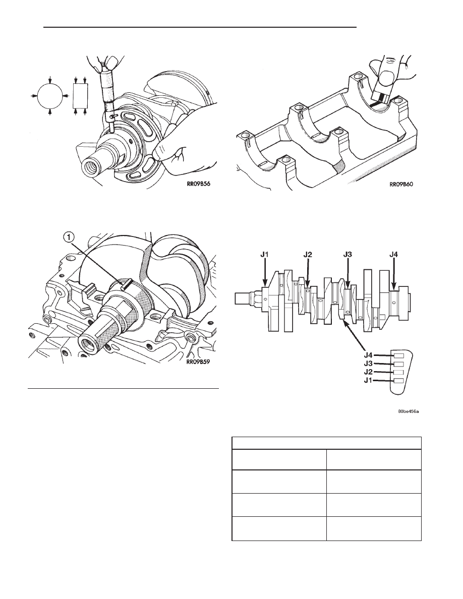
(1) Measure the crankshaft journal diameter and

confirm its classification from the Main Journal Size
Identification Chart. In the case of a bearing sup-
plied as a service part, the identification is embossed
at the position show in (Fig. 25).

NOTE: Service Replacement parts have identifica-
tion marks, but factory-assembled parts have no
identification marks. Service crankshaft identifica-
tion will have marks at counterweights (Fig. 24).

Fig. 21 Measure Crankshaft Journal O. D.

Fig. 22 Measure Oil Clearance with Plastigage

1 – PLASTIC GAUGE

Fig. 23 Measuring Clearance

Fig. 24 Crankshaft Size Identification

MAIN JOURNAL SIZE IDENTIFICATION

SERVICE PART

MARKING (Fig. 25)

JOURNAL OUTER

DIAMETER

0

59.994–60.000 mm

(2.3620–2.3622 in.)

1

59.988–59.994 mm

(2.3617–2.3620 in.)

2

59.982–59.988 mm

(2.3615–2.3617 in.)

JX

ENGINE

9 - 21

SERVICE PROCEDURES (Continued)

(2) The identification mark for the diameter of the

cylinder block bearing bore is embossed as shown in
(Fig. 26), starting from the # 1 mark at the front of
the engine.

(3) Select and install the bearings according to

these marks. Using the chart below, select the proper
bearing by using the markings on the crankshaft and
block. For a example:

(a) If the crankshaft journal outer diameter is

60.000 mm (2.3622 in.), the service part classifica-
tion will be “0” and the identification mark will be
“0”.

(b) If the identification mark for the cylinder

block main bore is “II”, select the bearing “2”
according the chart below.

Block Identification Mark

I

II

III

Main Journal
Identification

Mark

0

1

2

3

1

2

3

4

2

3

4

5

CRANKSHAFT END PLAY

(1) Mount a dial indicator to front of engine, locat-

ing

probe

on

nose

of

crankshaft

(Fig.

27).

(2) Move crankshaft all the way to the rear of its

travel.

(3) Zero the dial indicator.

(4) Move crankshaft all the way to the front and

read the dial indicator. Refer to Engine Specifica-
tions.

CAMSHAFT END PLAY

(1) Oil camshaft journals and install camshaft

without rocker arm assemblies.

(2) Using a suitable tool, move camshaft as far

rearward as it will go.

(3) Zero dial indicator (Fig. 28).
(4) Move camshaft as far forward as it will go.
(5) End play travel: 0.1 - 0.2 mm (0.004 - 0.008

in.). Max. Travel: 0.4 mm (0.016 in.)

Fig. 25 Bearing Identification

1 – IDENTIFICATION MARK

Fig. 26 Cylinder Block Bearing Bore Markings

Fig. 27 Crankshaft End Play—Typical

Fig. 28 Camshaft End Play

9 - 22

ENGINE

JX

SERVICE PROCEDURES (Continued)

REMOVAL AND INSTALLATION

ENGINE MOUNTS—FRONT AND REAR

REMOVAL

FRONT MOUNT

(1) Raise vehicle on hoist.
(2) Remove through bolt (A) at front mount (Fig.

30).

(3) Remove attaching bolts from mount to lower

radiator support crossmember.

NOTE: It may be necessary to tilt engine for front
mount removal clearance.

(4) Remove front mount.

REAR MOUNT

(1) Raise vehicle on hoist.
(2) Remove through bolt (A) from rear engine

mount and bracket (Fig. 31).

(3) Remove rear strut bracket (Fig. 29).
(4) Remove bolts attaching rear mount to cross-

member.

NOTE: It may be necessary to tilt engine for rear
mount removal clearance.

(5) Remove rear mount.

INSTALLATION

FRONT MOUNT

(1) Position front mount. Install front mount to

lower radiator support crossmember attaching bolts.
Tighten bolts to 61 N·m (45 ft. lbs.)

(2) Install through bolt (A) (Fig. 30).
(3) Tighten front through bolt (A) to 61 N·m (45 ft.

lbs.) (Fig. 30).

(4) Lower vehicle.

Fig. 29 Engine Mounting—Front and Rear

1 – LOWER RADIATOR SUPPORT
2 – FRONT ENGINE MOUNT
3 – DAMPER WEIGHT (SOME MODELS)
4 – REAR STRUT BRACKET
5 – SUPPORT BRACKET (SOME MODELS)
6 – REAR ENGINE MOUNT

Fig. 30 Engine Mounting—Front 2.5L

1 – FRONT TORQUE BRACKET
2 – SUPPORT
3 – STRUT

Fig. 31 Engine Mounting—Rear 2.5L

1 – REAR TORQUE BRACKET
2 – ENGINE
3 – TRANSMISSION
4 – REAR MOUNT

JX

ENGINE

9 - 23

REAR MOUNT

(1) Position rear mount.
(2) Install bolts attaching rear mount to suspen-

sion crossmember. Tighten bolts to 61 N·m (45 ft.
lbs.).

(3) Install rear strut bracket (Fig. 29). Tighten

bolts to 61 N·m (45 ft. lbs.).

(4) Install through bolt (A) and tighten 61 N·m (45

ft. lbs.) (Fig. 31).

(5) Lower vehicle

ENGINE MOUNT—RIGHT/ENGINE SUPPORT
BRACKET

NOTE: The right side engine mount is a Hydro-
Mount and may show surface cracks. This will not
effect it’s performance and should not be replaced.
Only replace the Hydro-Mount when it’s leaking
fluid.

(1) Raise vehicle on a hoist and remove inner

splash. Remove the right engine support assembly
vertical fasteners from frame rail (Fig. 32).

(2) Lower vehicle. Remove the load on the engine

motor mounts by carefully supporting the engine
assembly with a floor jack.

(3) Remove the three bolts attaching the engine

support assembly to the engine bracket.

(4) Move the air conditioning dryer aside.
(5) Remove coolant recovery system tank. Refer to

Group 7, Cooling System for procedure.

(6) Remove right engine support.
(7) Remove the three bolts attaching the engine

support bracket to the cylinder block.

NOTE: If centering or adjusting the engine/trans-
mission assembly is needed refer to Adjustments,
in this section.

(8) Reverse removal procedure for installation.

Refer to (Fig. 32) for bolt tightening specifications.

ENGINE MOUNT—LEFT

NOTE: If centering or adjusting the engine/trans-
mission assembly is needed refer to Adjustments,
in this section.

The left side engine mount is a Hydro-Mount and

may show surface cracks. This will not effect it’s
performance and should not be replaced. Only
replace the Hydro-Mount when it’s leaking fluid.

REMOVAL

(1) Support the transmission with a transmission

jack.

(2) Remove the three vertical bolts (A) from the

mount to the transmission bracket (Fig. 33).

(3) Remove the mount to frame rail fasteners (B)

and remove mount (Fig. 33).

INSTALLATION

(1) Install mount. Tighten mount to frame rail fas-

teners (B) to 33 N·m (24 ft. lbs.) (Fig. 33).

(2) If removed, install transmission bracket and

tighten bolts (C) and (D) to 61 N·m (45 ft. lbs.) (Fig.
33).

(3) Install mount to transmission bracket vertical

bolts (A). Tighten to 61 N·m (45 ft. lbs.) (Fig. 33).

ENGINE ASSEMBLY

REMOVAL

(1) Perform fuel pressure release procedure. Refer

to Group 14, Fuel System for procedure. Remove fuel
line to fuel rail.

(2) Disconnect negative cable from battery remote

jumper terminal.

(3) Remove Powertrain Control Module (PCM)

attaching screws and set aside.

(4) Drain cooling system. Refer to Group 7, Cooling

System for procedure.

(5) Remove upper radiator hose, radiator and fan

module. Refer to Group 7, Cooling System for proce-
dure.

(6) Remove lower radiator hose.
(7) Disconnect automatic transaxle cooler lines and

plug.

(8) Disconnect transaxle shift linkage.
(9) Disconnect throttle body linkage.
(10) Disconnect engine wiring harness.
(11) Disconnect heater hoses.

Fig. 32 Engine Mounting—Right Side 2.5L

1 – RIGHT ENGINE SUPPORT ASSEMBLY
2 – FRAME RAIL

9 - 24

ENGINE

JX

REMOVAL AND INSTALLATION (Continued)


Content   ..  368  369  370  371   ..