Chrysler Crossfire. Manual - part 72
RIGHT FRONT WHEEL SPEED SENSOR CIRCUIT (CONTINUED)
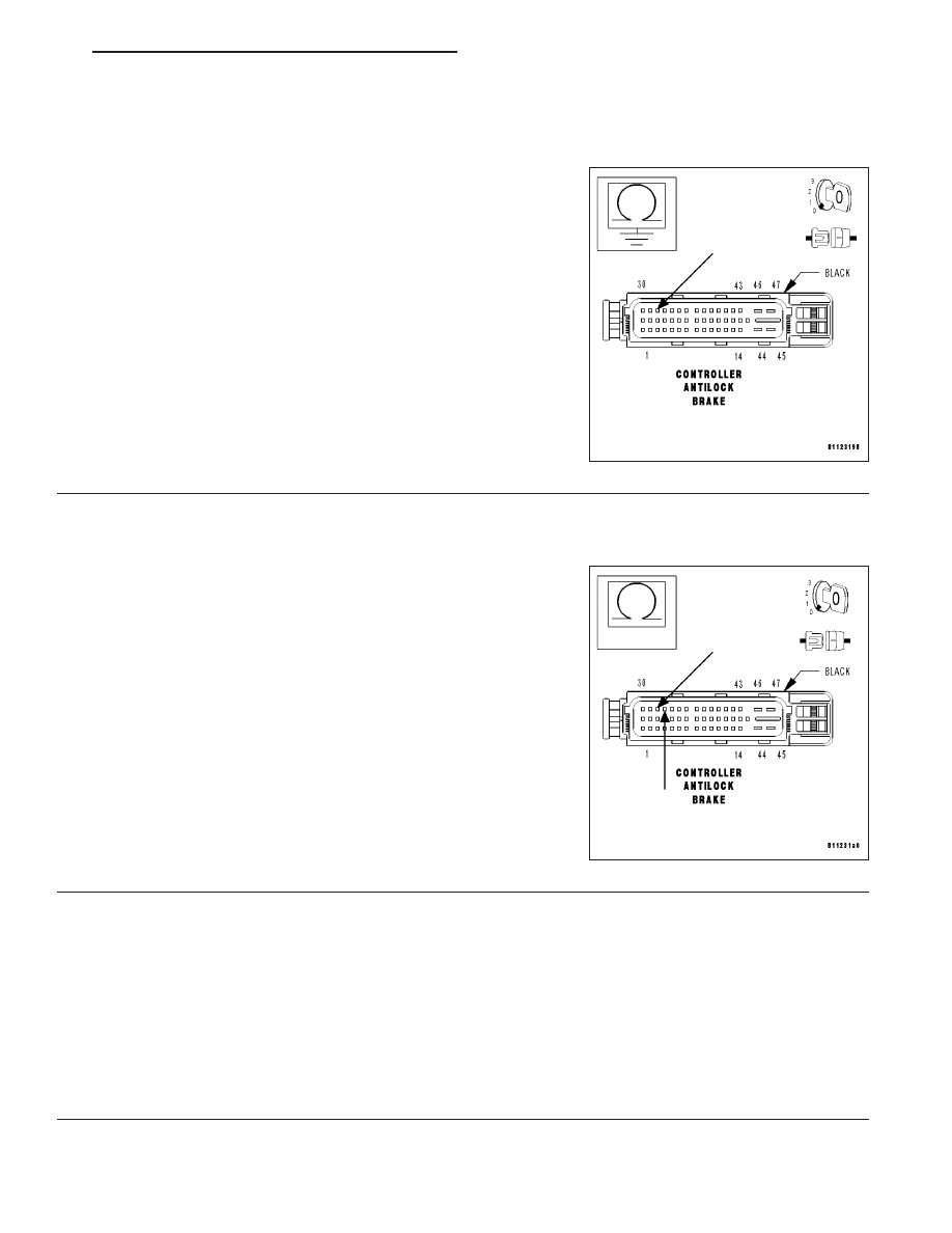
11.
MEASURE THE RESISTANCE BETWEEN GROUND AND THE RIGHT FRONT WHEEL SPEED SENSOR
SIGNAL CIRCUIT
With the ignition off.
Disconnect the CAB harness connector.
Note: Check connectors - Clean/repair as necessary.
Measure the resistance between ground and the Right Front Wheel
Speed Sensor Signal circuit at the CAB harness connector.
Is the resistance below 100 kohms?
Yes
>> Repair the Right Front Wheel Speed Sensor Signal circuit
for a short to ground.
Perform ABS VERIFICATION TEST.
No
>> Go to 12
12.
MEASURE THE RESISTANCE BETWEEN THE RIGHT FRONT WHEEL SPEED SENSOR 12 VOLT
SUPPLY CIRCUIT AND THE SENSOR SIGNAL CIRCUIT
With the ignition off.
Measure the resistance between the Right Front Wheel Speed Sensor
12 Volt Supply circuit and the Right Front Wheel Speed Sensor Signal
circuit at the CAB harness connector.
Is the resistance below 100 kohms?
Yes
>> Repair the Right Front Wheel Speed Sensor 12 Volt Sup-
ply circuit for a short to the Right Front Wheel Speed Sen-
sor Signal circuit.
Perform ABS VERIFICATION TEST.
No
>> Replace the Controller Antilock Brake. (Refer to 8 - ELEC-
TRICAL/ELECTRONIC CONTROL MODULES/CONTROL-
LER ANTILOCK BRAKE - REMOVAL).
Perform ABS VERIFICATION TEST.
13.
VISUALLY INSPECT COMPONENTS FOR DAMAGE AND CORRECT INSTALLATION
Visually inspect the related wiring harness and connectors. Look for any chafed, pierced, pinched, or partially bro-
ken wires. Look for broken, bent, pushed out, or corroded terminals.
Visually inspect the Right Front Wheel Speed Sensor, connector and tone wheel for damage and correct installation.
Are there any visible Sensor, connector or tone wheel concerns?
Yes
>> Correct the sensor, connector or tone wheel concerns as necessary.
Perform ABS VERIFICATION TEST.
No
>> Go to 14
ZH
BRAKES - ABS ELECTRICAL DIAGNOSTICS
5 - 121