Content .. 1163 1164 1165 1166 ..
Chrysler 300/300 Touring/300C, Dodge Magnum. Manual - part 1165
P1604-PCM INTERNAL DUAL-PORT RAM READ/WRITE INTEGRITY FAILURE
For a complete wiring diagram Refer to Section 8W.
•
When Monitored:
Ignition on and battery voltage greater than 10 volts.
•
Set Condition:
Internal PCM failure detected. One Trip Fault. Three good trips to turn off the MIL.
Possible Causes
PCM FUSED IGNITION SWITCH CIRCUIT
PCM INTERNAL
Always perform the Pre-Diagnostic Troubleshooting procedure before proceeding. (Refer to 9 - ENGINE -
DIAGNOSIS AND TESTING).
Diagnostic Test
1.
PCM IGNITION CIRCUITS
Turn the ignition off.
Disconnect the PCM harness connectors.
Ignition on, engine not running.
CAUTION: Do not probe the PCM harness connectors. Probing the
PCM harness connectors will damage the PCM terminals resulting
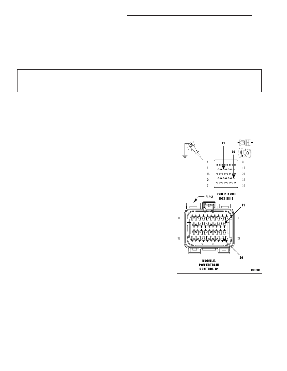
in poor terminal to pin connection. Install Miller Special Tool #8815
to perform diagnosis.
With a 12-volt test light connected to ground and with special tool
#8815 installed, probe the (F202) and (F924) Fused Ignition Switch cir-
cuits.
Perform the above check with the Ignition key in the off lock position,
Ignition on, engine not running position, and during cranking.
Wiggle the related wire harness while probing the special tool with the
test light to try to interrupt the circuit.
Does the test light illuminate brightly?
Yes
>> Go To 2
No
>> Repair the open or excessive resistance in the (F202) and
(F924) Fused Ignition Switch (Off, Run, Start) circuits.
Inspect the related fuse, if the fuse is open check the cir-
cuits for a short to ground.
Perform the POWERTRAIN VERIFICATION TEST. (Refer
to 9 - ENGINE - STANDARD PROCEDURE)
2.
PCM
The Powertrain Control Module is reporting internal errors.
9 - 684
ENGINE ELECTRICAL DIAGNOSTICS
LX