Chery Tiggo 5 (T21). Manual - part 480


  Index      Chery     Chery Tiggo 5 (T21) - service repair manual 2014 year


Search            


Content   ..  478  479  480  481   ..


Chery Tiggo 5 (T21). Manual - part 480


44–

12

44

Rear View Mirror Adjustment Switch Assembly

Removal

1. Turn off all the electrical equipment and ignition switch.
2. Disconnect the negative battery cable.
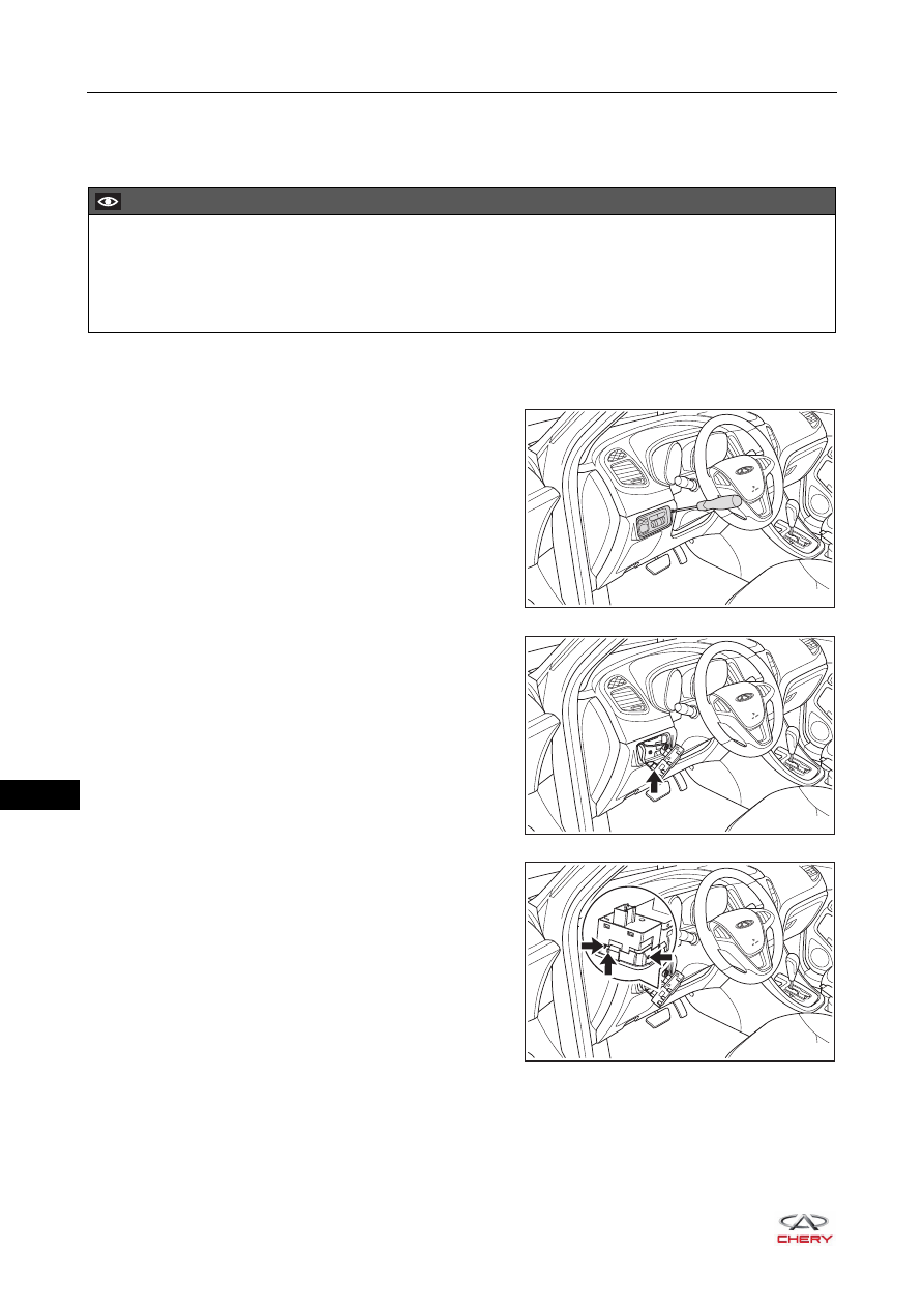
3. Remove the rear view mirror adjustment switch 

assembly.
a. Using a screwdriver wrapped with protective tape, pry 

out the headlight adjustment switch unit panel.

b. Disconnect the rear view mirror adjustment switch 

connector (arrow).

c. Using a screwdriver wrapped with protective tape, 

detach the claws (arrow) of rear view mirror 
adjustment switch assembly.

d. Remove the rear view mirror adjustment switch assembly.

CAUTION

 Make sure to wear safety equipment to prevent accidents when removing rear view mirror adjustment              

switch assembly.

 Prevent instrument panel lower left protector assembly from being scratched when removing rear view             

mirror adjustment switch assembly.

RT21440120

RT21440130

RT21440140

44–

13

44

Inspection

Check the outside rear view mirror adjustment switch 
assembly. 

a. Adjust the rear view mirror adjustment switch 

assembly to "L" position.

b. Using a multimeter, check for continuity between 

terminals of rear view mirror adjustment switch 
assembly according to the table below.

If result is not as specified, replace rear view mirror 
adjustment switch assembly.

c. Adjust the rear view mirror adjustment switch 

assembly to "R" position.

d. Using a multimeter, check for continuity between 

terminals of rear view mirror adjustment switch 
assembly according to the table below.

If result is not as specified, replace rear view mirror 
adjustment switch assembly.

L

R

1 2

3 4 5

6 7

8 9 10

-

+

RT21440150

Multimeter 

Connection

Switch 

Condition

Specified 

Condition

Terminal 3 - 7
Terminal 4 - 5

UP

Continuity

OFF

No continuity

Terminal 3 - 5
Terminal 4 - 7

DOWN

Continuity

OFF

No continuity

Terminal 3 - 6
Terminal 4 - 5

LEFT

Continuity

OFF

No continuity

Terminal 3 - 5
Terminal 4 - 6

RIGHT

Continuity

OFF

No continuity

L

R

1 2

3 4 5

6 7

8 9 10

-

+

RT21440150

Multimeter 

Connection

Switch 

Condition

Specified 

Condition

Terminal 3 - 8
Terminal 4 - 5

UP

Continuity

OFF

No continuity

Terminal 3 - 5
Terminal 4 - 8

DOWN

Continuity

OFF

No continuity

Terminal 3 - 9
Terminal 4 - 5

LEFT

Continuity

OFF

No continuity

Terminal 3 - 5
Terminal 4 - 9

RIGHT

Continuity

OFF

No continuity

44–

14

44

Installation

Installation is in the reverse order of removal.

CAUTION

 Always operate carefully to prevent components from being damaged when installing the rear view 

mirror adjustment switch assembly.

 Install each connector in place when installing rear view mirror adjustment switch assembly.
 Check that switch can operate normally after installing rear view mirror adjustment switch assembly.


Content   ..  478  479  480  481   ..