Chery Tiggo 5 (T21). Manual - part 466


  Index      Chery     Chery Tiggo 5 (T21) - service repair manual 2014 year


Search            


Content   ..  464  465  466  467   ..


Chery Tiggo 5 (T21). Manual - part 466


43–

44

43

WINDSHIELD/WINDOW GLASS

ON-VEHICLE SERVICE

Power Glass Regulating Control Master Switch

Removal

1. Turn off all the electrical equipment and ignition switch.
2. Disconnect the negative battery cable.
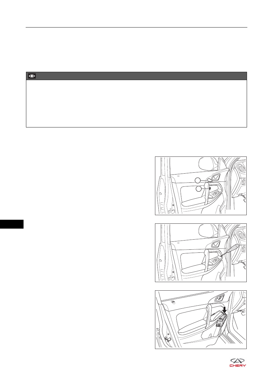
3. Remove the power glass regulating control master switch assembly.

a. Remove the cushion rubber (1) from power glass 

regulating control master switch assembly.

b. Remove the fixing screw (2) from power glass 

regulating control master switch assembly.

(Tightening torque: 2 ± 0.5 N·m)

c. Using a screwdriver wrapped with protective tape, pry 

up the power glass regulating control master switch 
assembly.

d. Disconnect the connector (arrow) from power glass 

regulating control master switch assembly, and 
remove the power glass regulating control master 
switch assembly.

CAUTION

 Make sure to wear safety equipment to prevent accidents when removing power glass regulating control 

master switch.

 Appropriate force should be applied when removing power glass regulating control master switch. Be 

careful not to operate roughly.

 Try to prevent front door protector assembly from being scratched when removing power glass regulating 

control master switch.

RT21430050

1

2

RT21430060

RT21430070

43–

45

43

4. Remove the power glass regulating control master 

switch.
a. Using a screwdriver wrapped with protective tape, pry 

up the claws (arrow) on power glass regulating control 
master switch, and remove the power glass regulating 
control master switch.

Inspection

1. Check power glass regulating control master switch.

a. Using a digital multimeter, check for continuity of 

power glass regulating control master switch 
according to the table below.

If result is not as specified, replace power glass 
regulating control master switch.

RT21430080

1
9

2 3 4 5 6 7 8

10111213141516

-

+

RT21430090

Area

Multimeter 

Connection

Switch 

Condition

Specified 

Condition

Front left door
glass
regulating
switch

6 - 8

UP

220 Ω

OFF

No continuity

6 - 8

DOWN

Continuity

OFF

No continuity

Front right
door glass
regulating
switch

5 - 11

UP

220 Ω

OFF

No continuity

5 - 11

DOWN

Continuity

OFF

No continuity

Rear left door
glass
regulating
switch

4 - 11

UP

220 Ω

OFF

No continuity

4 - 11

DOWN

Continuity

OFF

No continuity

Rear right
door glass
regulating
switch

3 - 11

UP

220 Ω

OFF

No continuity

3 - 11

DOWN

Continuity

OFF

No continuity

43–

46

43

2. Check power glass regulating control master switch illumination.

a. Apply battery voltage to the terminals of power glass 

regulating control master switch connector, and check 
the operation of power glass regulating control master 
switch according to the table below.

If result is not as specified, replace power glass 
regulating control master switch.

Installation

Installation is in the reverse order of removal.

1
9

2 3 4 5 6 7 8

10111213141516

RT21430091

-

+

Measurement Condition

Specified 

Condition

Battery positive 

(+)

Battery negative 

(-)

13

12

LED comes on

CAUTION

 Check if connector is correctly installed when installing power glass regulating control master switch.
 Check if switch operates normally after installing glass regulating control master switch.

43–

47

43

Front Door Outer Weather bar

Removal

HINT:

 Use the same procedures for the right side and left side.

 Procedures listed below are for the left side.

1. Turn off all the electrical equipment and ignition switch.
2. Disconnect the negative battery cable.
3. Remove the outside rear view mirror assembly (

See page 44-7

).

4. Remove the front left door outer weather bar.

a. Remove the front left door frame weatherstrip.

HINT:
It is not necessary to remove the front left door frame weatherstrip completely. There is a fixing screw in 
the front door frame weatherstrip.

b. Remove 2 fixing screws (arrow) from front door outer 

weather bar.

(Tightening torque: 1.3 ± 0.2 N·m)

c. Remove the front left door outer weather bar in the 

direction of arrow as shown in the illustration.

CAUTION

 Make sure to wear safety equipment to prevent accidents when removing front door outer weather bar.
 Appropriate force should be applied when removing front door outer weather bar. Be careful not to 

operate roughly.

 Try to prevent body paint surface from being scratched when removing front door outer weather bar.

RT21430160

RT21430170


Content   ..  464  465  466  467   ..