Chery Tiggo 5 (T21). Manual - part 440
 

  Index      Chery     Chery Tiggo 5 (T21) - service repair manual 2014 year


Search            


Content   ..  438  439  440  441   ..


Chery Tiggo 5 (T21). Manual - part 440


38–

41

38

Self-diagnosis Detection Logic

Diagnosis Procedure

a. Use X-431 3G diagnostic tester (the latest software) to clear the DTCs stored in the instrument cluster 

control system.

b. Turn ignition switch to LOCK and wait for a few seconds.
c. Turn ignition switch to ON.
d. Use X-431 3G diagnostic tester (the latest software) to read the DTCs in the instrument cluster control 

system again.

e. Read the DTCs.

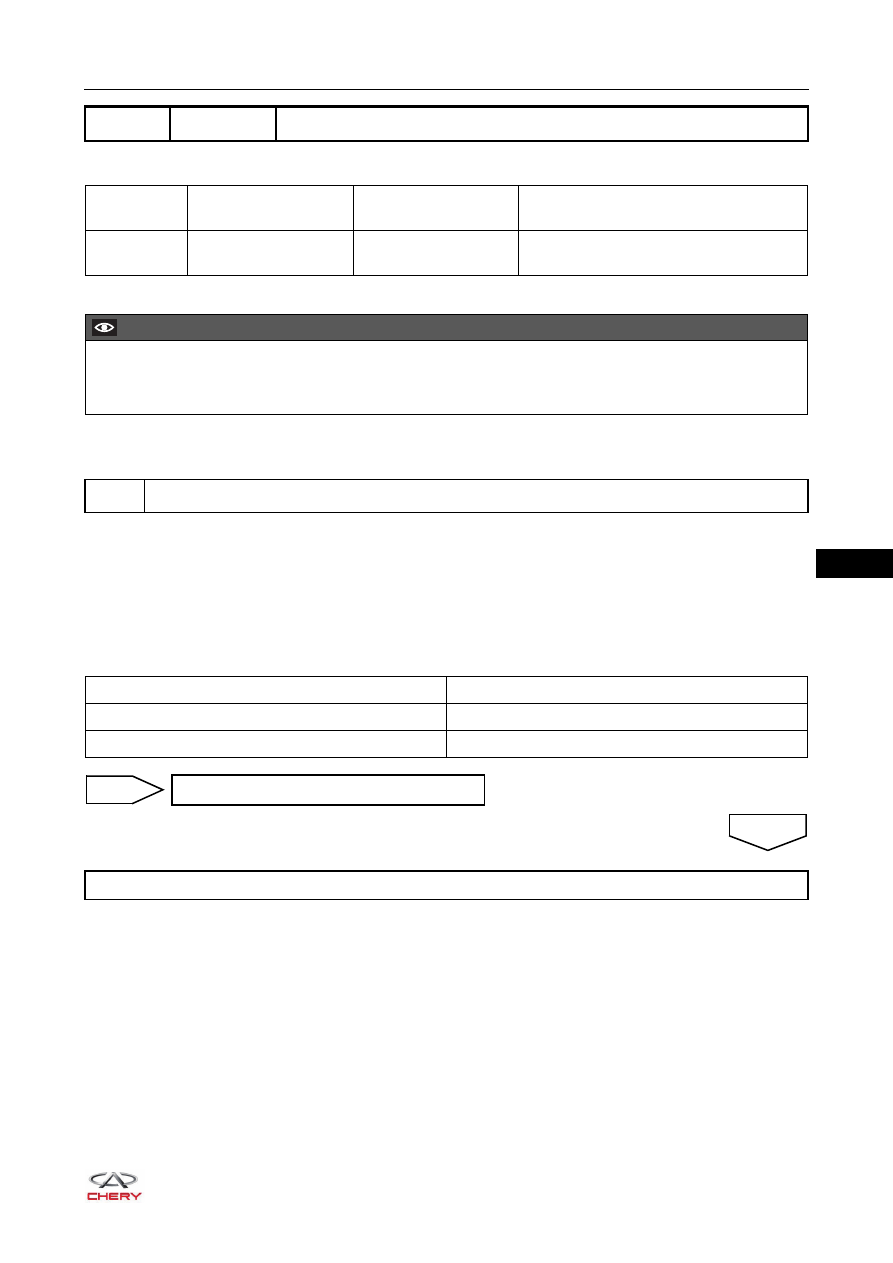
DTC

U1300-55 Software Configuration Error, Not Configured

DTC Code

DTC Definition

DTC Detection 

Condition

Possible Cause

U1300-55

Software Configuration 
Error, Not Configured

Ignition switch ON

 Instrument cluster

CAUTION

 When performing circuit diagnosis and test, always refer to circuit diagram for specific circuit and 

component information.

1

Reconfirm DTCs

Result

Proceed to

DTC U1300-55 is output

NG

No DTC is output

OK

Replace instrument cluster

NG

System is normal

OK

38–

42

38

ON-VEHICLE SERVICE

Instrument Cluster

Removal

1. Turn off all the electrical equipment and ignition switch.
2. Disconnect the negative battery cable.
3. Lower the steering wheel in the direction of arrow as 

shown in the illustration.

4. Remove the combination switch cover (

See page 28-13

).

5. Remove the instrument cluster.

a. Remove 2 fixing screws (arrow) from instrument 

cluster.

(Tightening torque: 1.5 ± 0.5 N·m)

b. Using a screwdriver wrapped with protective tape, pry 

up the clips on instrument cluster.

CAUTION

 Be sure to wear safety equipment to prevent accidents when removing instrument cluster.
 Operate carefully to prevent components from being damaged when removing instrument cluster.
 DO NOT scratch interior and body paint when removing instrument cluster.

RT21380040

RT21380020

RT21380021

38–

43

38

c. Disconnect the instrument cluster connector (arrow), 

and remove the instrument cluster.

Installation

Installation is in the reverse order of removal.

RT21380030

CAUTION

 When installing instrument cluster, be sure to align instrument cluster positioning hole with instrument 

panel dowel pin, and clips are clamped in place.

 When installing instrument cluster, be sure to install connector in place.
 When installing instrument cluster, be sure to tighten fixing screws in place.
 Operate carefully to prevent other components from being damaged when installing instrument cluster.

38–

44


Content   ..  438  439  440  441   ..