Chery Tiggo 5 (T21). Manual - part 391
35–
39
35
ET21350160
R
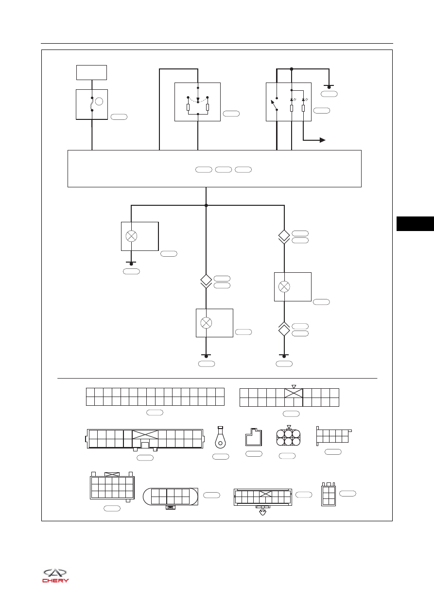
E1
BATTERY
60A
MF03
ENGINE
COMPARTMENT
FUSE AND
RELAY BOX
COMBINATION
LIGHT SWITCH
3
E1
BCM
3
GR
GR
C6
A32
A27
10
9
12
TURN
SIGNAL
LIGHT
TURN
SIGNAL
LIGHT
B
GR
B
3
1
B
10
2
330
150
RIGHT
LEFT
W
A17
1
YR
A1
3
4
2
5
GrB
B
1
2
3
4
5
11
12
13
14
15
6
7
8
9
10
22 21 20 19 18 17
16
C1
C10 C11 C12 C13 C14 C15 C16 C17 C18
C2 C3 C4 C5
C6 C7 C8 C9
C20
C19
E-061
E-061
I-011
HAZARD SWITCH
I-001
E-072
I-005
B-043
FRONT
RIGHT
HEADLIGHT
E-034
B-048
E-070
REAR
RIGHT
COMBI-
NATION
LIGHT
B-016
B-018
TURN
SIGNAL
LIGHT
GR
GR
13
4
BB
B-062
E-031
W
E-072
A32
A31
A30
A29
A28
A16
A15
A14
A13
A12
A11
A10
A9
A8
A7
A6
A5
A4
A3
A2
A1
A27
A26
A25
A24
A23
A22
A21
A20
A19
A18
A17
L
I-005
1
2
3
4
5
6
7
8
9
10
B
I-011
W
B-043
1
2
3
4
5
6
B
B-016
W
B-048
B
E-034
9
7
5
3
1
10 8
6
4
2
15
B-061
H-002
3
B-061
H-002
POWER
REAR
VIEW
MIRROR
MOTOR
H-008
1
4
7 10 13 16
2
5
8 11 14 17
3
6
9 12 15 18
W
B-061
1
2
3
8
9
10
11
12
13
14
15
16
4
5
6
7
W
H-008
I-003
1
2
3
4
5
6
B
I-001
Lg
ILLUMINATION