Chery Tiggo 5 (T21). Manual - part 347


  Index      Chery     Chery Tiggo 5 (T21) - service repair manual 2014 year


Search            


Content   ..  345  346  347  348   ..


Chery Tiggo 5 (T21). Manual - part 347


31–

92

31

HINT:
Resistance decreases as the temperature increases.

If result is not as specified, replace the evaporator temperature sensor.

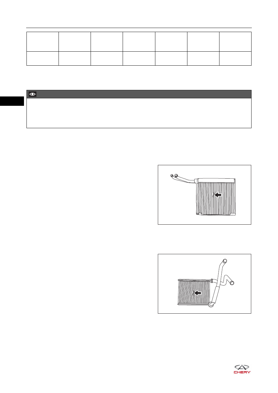
2. Check the evaporator core assembly.

a. Check if the evaporator core assembly is cracked, damaged and leaked.

If any problem is found, replace the evaporator core assembly.

b. Check the fin for bends.

If any fin is bent, carefully straighten it with a 
screwdriver or pliers.

3. Check the heater core assembly.

a. Check if the heater core assembly is cracked, damaged or leaked.

If any problem is found, replace the heater core assembly.

b. Check the fin for bends.

If any fin is bent, carefully straighten it with a 
screwdriver or pliers.

Terminal 1 - 
Terminal 2

-9

9316

23

2388

55

776

Multimeter 

Connection

Temperature 

(°C)

Specified 

Condition 

(Ω)

Temperature 

(°C)

Specified 

Condition 

(Ω)

Temperature 

(°C)

Specified 

Condition 

(Ω)

CAUTION

 Resistance value may change even if the sensor is touched slightly. Make sure that the connector of 

sensor is held firmly. 

 During measurement, the sensor temperature must be almost the same as the ambient temperature.

RT21310730

RT21310740

31–

93

31

4. Check the damper control mechanism assembly.

a. Check if the mode damper adjustment mechanism set is stuck, fell out, deformed or damaged. Replace 

as necessary.

b. Check if the inner/outer circulation/temperature/face/defrost/foot damper set is stuck, fell out, deformed 

or damaged. Replace as necessary.

Assembly

Assembly is in the reverse order of disassembly.

Installation

Installation is in the reverse order of removal.

CAUTION

 If evaporator core is to be reused, do not insert the evaporator temperature sensor into a location where 

the sensor was previously inserted. Insert it to a location that is 1 fin to the right or left of its previous 
location.

 During installation, apply a small amount of grease to the contact surface of mode damper adjustment 

mechanism set to ensure that it can operate smoothly.

 Always check that inner/outer circulation damper mechanism assembly operates normally after 

installation is completed.

 Always check that mode damper mechanism assembly operates normally after installation is completed.
 Always check that temperature damper mechanism assembly operates normally after installation is 

completed.

CAUTION

 Tighten fixing bolts and fixing nuts to specified torque.
 It is necessary to replace the refrigerant line O-ring when installing the refrigerant line. Failure to do so 

may result in refrigerant leaks.

 Lubricate the new rubber O-ring with clean refrigerant oil and install it to the refrigerant line joint.
 Only use the specified O-ring, as it is made of special materials for R134a system.
 Only use recommended refrigerant oil which is applicable to the A/C compressor assembly on vehicle.
 Be sure to recharge the refrigerant and check refrigerant fo leakage after installation. 

31–

94

31

A/C Low Pressure Line

Removal

1. Recover the refrigerant from the A/C system (

See page 31-66

).

2. Turn off all the electrical equipment and ignition switch.
3. Disconnect the negative battery cable.
4. Remove the A/C low pressure line (compressor to evaporator). 

a. Remove the fixing bolt (arrow) between A/C high/low 

pressure line and expansion valve, and detach the A/C 
low pressure line.

(Tightening torque: 7 ± 1 N·m)

b. Remove the coupling nut (arrow) between A/C high/low 

pressure line fixing bracket and body, and disengage 
the A/C low pressure line.

(Tightening torque: 7 ± 1 N·m) 

c. Remove the coupling nut (arrow) between A/C high/

low pressure line fixing bracket and body, and 
disengage the A/C low pressure line.

(Tightening torque: 7 ± 1 N·m)

CAUTION

 Special service equipment for R134a refrigerant must be used to recover/charge refrigerant.
 Always keep the work area in good ventilation.
 The disconnected A/C line and connecting part should be sealed to prevent foreign matter from entering.

RT21310260

RT21310750

RT21310760

31–

95

31

d. Disengage the fixing clamp (arrow) between A/C low 

pressure line and coolant circulation line.

e. Remove the fixing bolt (arrow) between A/C low 

pressure line and compressor assembly, and 
disengage the A/C low pressure line from the 
compressor assembly.

(Tightening torque: 25 ± 2.5 N·m)

f. Remove the A/C low pressure line (compressor to evaporator). 

Installation

Installation is in the reverse order of removal.

RT21310770

RT21310780

CAUTION

 Tighten fixing bolts and fixing nuts to specified torque.
 It is necessary to replace the refrigerant line O-ring when installing the refrigerant line. Failure to do so 

may result in refrigerant leaks.

 Lubricate the new rubber O-ring with clean refrigerant oil and install it to the refrigerant line joint.
 Only use the specified O-ring, as it is made of special materials for R134a system.
 Only use recommended refrigerant oil which is applicable to the A/C compressor assembly on vehicle.
 Perform recharging for the A/C system and check refrigerant for leakage.


Content   ..  345  346  347  348   ..