Chery Tiggo 5 (T21). Manual - part 342
31–
72
31
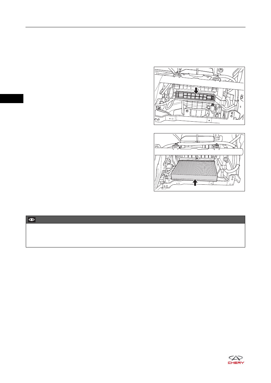
A/C Element
Removal
1. Remove the glove box assembly (
).
2. Remove the A/C element.
a. Detach the claws on both sides of A/C element cover,
and remove the A/C element cover (arrow) from the
air inlet assembly.
b. Pull out the A/C element (arrow) slowly from the air
inlet assembly.
Installation
Installation is in the reverse order of removal.
RT21310110
RT21310120
CAUTION
Be sure to check the A/C element for dirt during installation. Clean as necessary.
If A/C element is too dirty or damaged, replace with a new one.