Chery Tiggo 5 (T21). Manual - part 341


  Index      Chery     Chery Tiggo 5 (T21) - service repair manual 2014 year


Search            


Content   ..  339  340  341  342   ..


Chery Tiggo 5 (T21). Manual - part 341


31–

68

31

10.Remove the connecting pipe for refrigerant charging after the test is completed.
11.Reinstall the cover onto the A/C line joint.

Refrigerant Oil Recovering

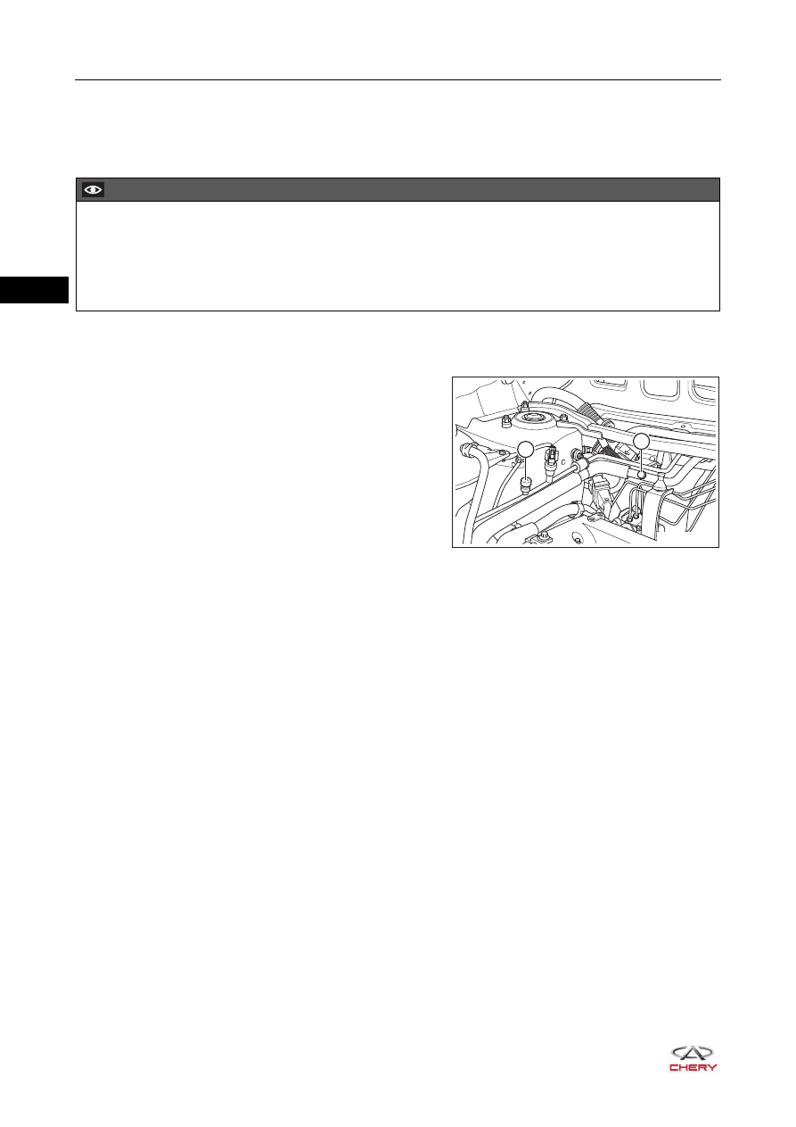
1. Open the engine hood and loosen the joint cover of A/C high/low pressure line.
2. Connect the refrigerant recycling machine to A/C high/low pressure line joint.

a. Connect the red connector to A/C high pressure line 

joint (1).

b. Connect the blue connector to A/C low pressure line 

joint (2).

3. Open the high pressure valve and low pressure valve of refrigerant recycling machine.
4. Recover the refrigerant oil according to the instructions on machine.
5. Record the amount of recovered refrigerant oil.
6. Disconnect the connections between refrigerant recycling machine and A/C line joint.
7. Reinstall the joint cover onto the refrigerant line joint.

CAUTION

 Special service equipment for R134a refrigerant must be used.
 Always keep the work area in good ventilation, because the A/C system is easy to leak.
 Always dispose of the recovered refrigerant as specified.
 Refrigerant oil must be charged after replacing the A/C system components or recovering the refrigerant.

RT21310050

1

2

31–

69

31

Refrigerant Oil Charging

Refrigerant Oil Charging Amount Specifications

1. Perform vacuum pumping with vacuum pump. Wait for approximately 10 minutes after completing the 

operation, check if there is any change in A/C system pressure. If there is any change, A/C system 
leakage may exist, you should check and repair the A/C system. If there is no change, proceed to perform 
the refrigerant oil charging procedures.

2. Open the suction valve and close the exhaust valve, and then open the charge valve to allow the 

refrigerant oil to flow into the system.

3. Close the charging valve after the refrigerant oil charging is completed.
4. Perform the vacuum pumping again for 3 minutes.
5. Continue to perform refrigerant charging procedures after the operation is completed.

Item

A/C Compressor 

Assembly 

Replacement

Condenser 

Replacement

Evaporator 

Replacement

Line Replacement

Charging 

Capacity (ml)

It is necessary to pour 
out 50 ml of refrigerant 
oil from the new 
compressor assembly

50 ml

50 ml

10 ml

31–

70

31

A/C Control Panel Assembly

Removal

1. Turn off all the electrical equipment and ignition switch.
2. Disconnect the negative battery cable.
3. Remove the A/C control panel assembly.

a. Using a flat tip screwdriver wrapped with protective 

tape, pry out the console panel assembly carefully.

b. Disconnect the audio system connectors (arrow).

c. Remove 2 fixing screws (arrow) from the A/C control 

panel assembly, and detach the fixing clip on the 
lower part.

(Tightening torque: 2.5 ± 0.5 N·m)

d. Disconnect the A/C control panel assembly connector 

(arrow).

e. Remove the A/C control panel assembly.

RT21310060

12V 120W

RT21310070

RT21310080

RT21310090

3 5

4

2

R

1

31–

71

31

Inspection

1. Check the A/C control panel assembly.

a. Remove the A/C control panel assembly.
b. Connect the positive (+) battery lead to terminal 3 and 

negative (-) battery lead to terminal 4, then check if 
the A/C control panel assembly switch backlight 
comes on.
OK: Light comes on.

If result is not as specified, replace the A/C control panel assembly.

Installation

Installation is in the reverse order of removal.

-

+

RT21310100

1

20

21

40

CAUTION

 Be sure to install clip on the lower part of A/C control panel assembly in place during installation.
 Be sure to align the positioning hole on upper part of A/C control panel assembly with the dowel pin of 

instrument panel during installation.


Content   ..  339  340  341  342   ..