Chery Tiggo 5 (T21). Manual - part 314


  Index      Chery     Chery Tiggo 5 (T21) - service repair manual 2014 year


Search            


Content   ..  312  313  314  315   ..


Chery Tiggo 5 (T21). Manual - part 314


29–

14

29

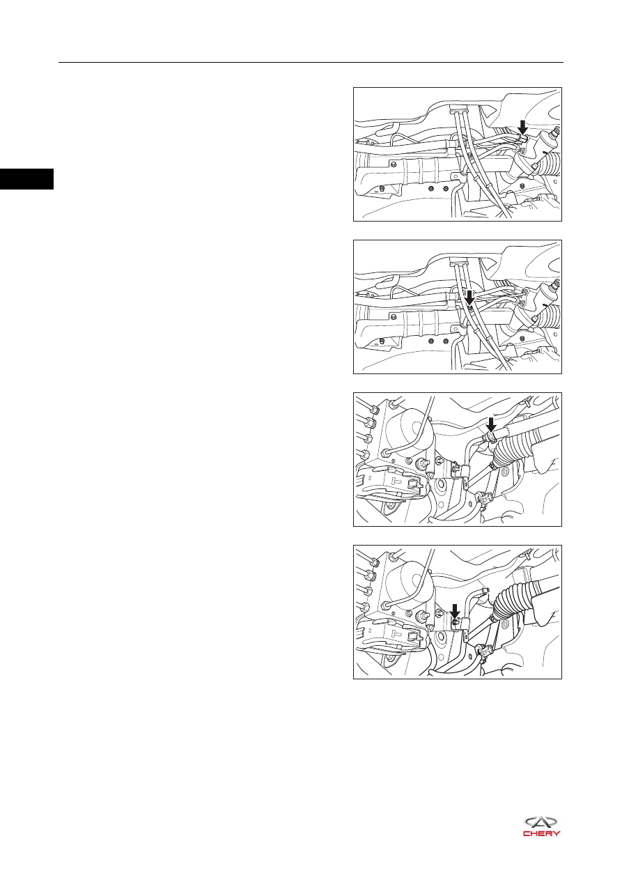
5. Remove the fluid return pipe.

a. Remove the fluid return pipe clamping bolt from the 

steering gear assembly.

(Tightening torque: 30 ± 3 N·m)

b. Remove the fluid return pipe bracket bolt 1 (arrow).

(Tightening torque: 9 ± 1 N·m)

c. Loosen the fluid return pipe 1 clamp and disconnect 

the fluid return pipe joint.

d. Remove the fluid return pipe bracket nut 2 (arrow).

(Tightening torque: 7 ± 1 N·m)

RT21290062

RT21290063

RT21290080

RT21290081

29–

15

29

e. Remove the fluid return pipe bracket bolt 3 (arrow).

(Tightening torque: 7 ± 1 N·m)

f. Remove the fluid return pipe bracket nut 4 (arrow).

(Tightening torque: 7 ± 1 N·m)

g. Remove the fixing bolt (arrow) and remove the guide 

pipe.

(Tightening torque: 7 ± 1 N·m)

h. Remove the fluid return pipe 2 carefully.

6. Remove the cooling pipe.

a. Remove 3 plastic clamps (arrow) from the right 

radiator deflector, and remove the right radiator 
deflector.

RT21290090

RT21290100

RT21290101

RT21290102

29–

16

29

b. Remove the cooling pipe bracket nut 1.

(Tightening torque: 7 ± 1 N·m)

c. Move away the clamp (arrow) between cooling pipe 

and fluid return pipe, and disconnect the connection 
between cooling pipe and fluid return pipe.

d. Remove the cooling pipe bracket nut 2 (arrow).

(Tightening torque: 7 ± 1 N·m)

e. Remove the cooling pipe carefully.

Inspection

1. Check steering fluid pipe for cracks, wear or blockage. Replace steering fluid pipe assembly if necessary.
2. Check steering fluid pipe joint and O-ring for deformation or damage. Replace steering fluid pipe assembly 

if necessary.

3. Check if steering fluid pipe bracket is normal. Replace if necessary.

Installation

Installation is in the reverse order of removal.

1

RT21290110

RT21290120

CAUTION

 Never tap or squeeze steering fluid pipe.
 Tighten fixing nut to the specified torque.

29–

17

29

Power Steering Pump Assembly

Removal

1. Drain steering fluid (

See page 29-7

).

2. Remove the accessory drive belt (

See page 07-24

).

3. Remove the power steering pump with bracket assembly.

a. Remove the high pressure fluid pipe joint hollow bolt 

(1).

(Tightening torque: 45 ± 5 N·m)

b. Loosen the elastic clamp (2), and disconnect the 

connection between fluid suction pipe and power 
steering pump assembly.

c. Remove 3 fixing bolts (1), (2) and (3) from the steering 

pump bracket and the fixing bolt (arrow) from the idler 
pulley.

(Tightening torque for steering pump bracket fixing 
bolt: 25 ± 3 N·m)

(Tightening torque for idler pulley fixing bolt: 50 ± 5 
N·m)

ENVIRONMENTAL PROTECTION

 Collect steering fluid flowing from the line with a container when disconnecting the line.

2

1

RT21290022

CAUTION

 Using a plug, clog the disconnected steering system line to prevent foreign matter from entering.

RT21290130

2

3

1


Content   ..  312  313  314  315   ..