Chery Tiggo 5 (T21). Manual - part 249


  Index      Chery     Chery Tiggo 5 (T21) - service repair manual 2014 year


Search            


Content   ..  247  248  249  250   ..


Chery Tiggo 5 (T21). Manual - part 249


22–

12

22

Front Steering Knuckle

Removal

HINT:

 Use the same procedures for the right side and left side. 

 Procedures listed below are for the left side. 
1. Remove the front left wheel (

See page 24-9

).

2. Remove the front drive shaft assembly locking nut (

See page 22-9

).

3. Remove the front left brake caliper assembly (

See page 26-28

).

4. Remove the front left brake disc (

See page 26-28

).

5. Remove the front left hub assembly (

See page 22-9

).

6. Remove the front left mudguard (

See page 22-9

).

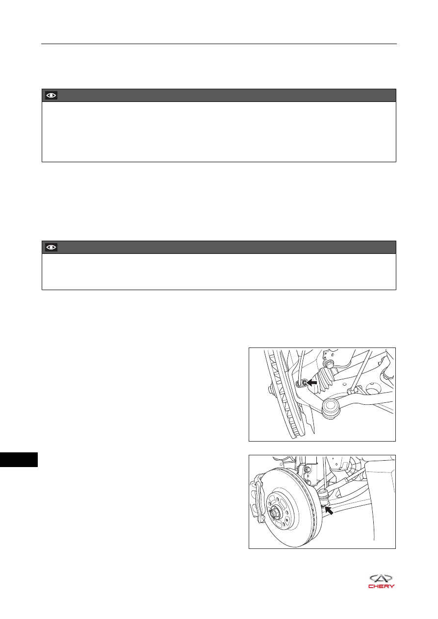
7. Remove the front left steering knuckle assembly.

a. Remove the coupling bolt (arrow) between front left 

wheel speed sensor and front left steering knuckle 
assembly, and disengage the front left wheel speed 
sensor carefully.

(Tightening torque: 10 ± 1 N·m)

b. Remove the locking nut (arrow) between left steering 

tie rod assembly ball pin and front left steering knuckle 
assembly.

(Tightening torque: 47 ± 3 N·m)

CAUTION

 Be sure to wear necessary safety equipment to prevent accidents. 
 Check if safety lock of lifter is locked when repairing chassis parts.
 It is not permitted to weld or modify bearing parts of wheel suspension and guide parts of wheel.
 When removing chassis parts, replace the self-locking nuts and rusted nuts for safety.

CAUTION

 Place front brake caliper assembly to a proper position after removal. Be careful not to extend front brake 

hose excessively.

RT21220110

RT21220120

22–

13

22

c. Install the ball pin separator (1), and tighten the ball 

pin separator bolt with a wrench (2) to separate the 
steering tie rod ball pin from the steering knuckle 
assembly.

d. Remove the lock pin (arrow) and coupling nut (1) 

between front left control arm assembly ball pin and 
front left steering knuckle assembly.

(Tightening torque: 120 ± 12 N·m)

e. Remove 2 coupling bolts and nuts (arrow) between 

front left shock absorber assembly and front left 
steering knuckle assembly.

(Tightening torque: 180 ± 10 N·m)

f. Detach the left drive shaft and remove the front left steering knuckle assembly.

Installation

Installation is in the reverse order of removal.

2

1

RT21220130

1

RT21220140

RT21220150

CAUTION

 Always tighten coupling bolts and nuts to the specified torque.
 Check and adjust front wheel alignment after installation.

22–

14

22

Side Rail Welding Assembly

Removal

1. Remove the side rail welding assembly.

a. Using an engine equalizer, support the engine and transmission assembly securely.
b. Remove 2 coupling bolts (arrow) between engine 

lower left protector assembly and side rail welding 
assembly.

(Tightening torque: 10 ± 1 N·m)

c. Remove 2 coupling bolts (arrow) between engine 

lower right protector assembly and side rail welding 
assembly.

(Tightening torque: 10 ± 1 N·m)

d. Remove the coupling bolt and nut (arrow) between 

rear mounting cushion assembly and rear mounting 
bracket.

(Tightening torque: 70 ± 5 N·m)

WARNING

 Be sure to wear necessary safety equipment to prevent accidents. 
 Check if safety lock of lifter is locked when repairing chassis parts.
 It is not permitted to weld or modify bearing parts of wheel suspension and guide parts of wheel.
 When removing chassis parts, replace the self-locking nuts and rusted nuts for safety.
 When removing side rail welding assembly, an engine equalizer needs to be used to support engine and 

transmission assembly securely to prevent them from being damaged.

RT21220160

RT21220170

RT21220180

22–

15

22

e. Remove the coupling bolt and nut (arrow) between 

front mounting cushion assembly and front mounting 
bracket.

(Tightening torque: 70 ± 5 N·m)

f. Remove 2 coupling bolts (arrow) between side rail 

welding assembly and body.

(Tightening torque: 80 ± 6 N·m)

g. Remove 2 coupling bolts (arrow) between side rail 

welding assembly and front mounting cushion 
assembly.

(Tightening torque: 70 ± 5 N·m)

h. Remove 2 coupling bolts and a nut (arrow) between 

side rail welding assembly and rear mounting cushion 
assembly.

(Tightening torque: 70 ± 5 N·m)

i. Remove the side rail welding assembly.

RT21220190

RT21220200

RT21220210

RT21220220


Content   ..  247  248  249  250   ..