Chery Tiggo 5 (T21). Manual - part 248


  Index      Chery     Chery Tiggo 5 (T21) - service repair manual 2014 year


Search            


Content   ..  246  247  248  249   ..


Chery Tiggo 5 (T21). Manual - part 248


22–

8

22

DIAGNOSIS & TESTING

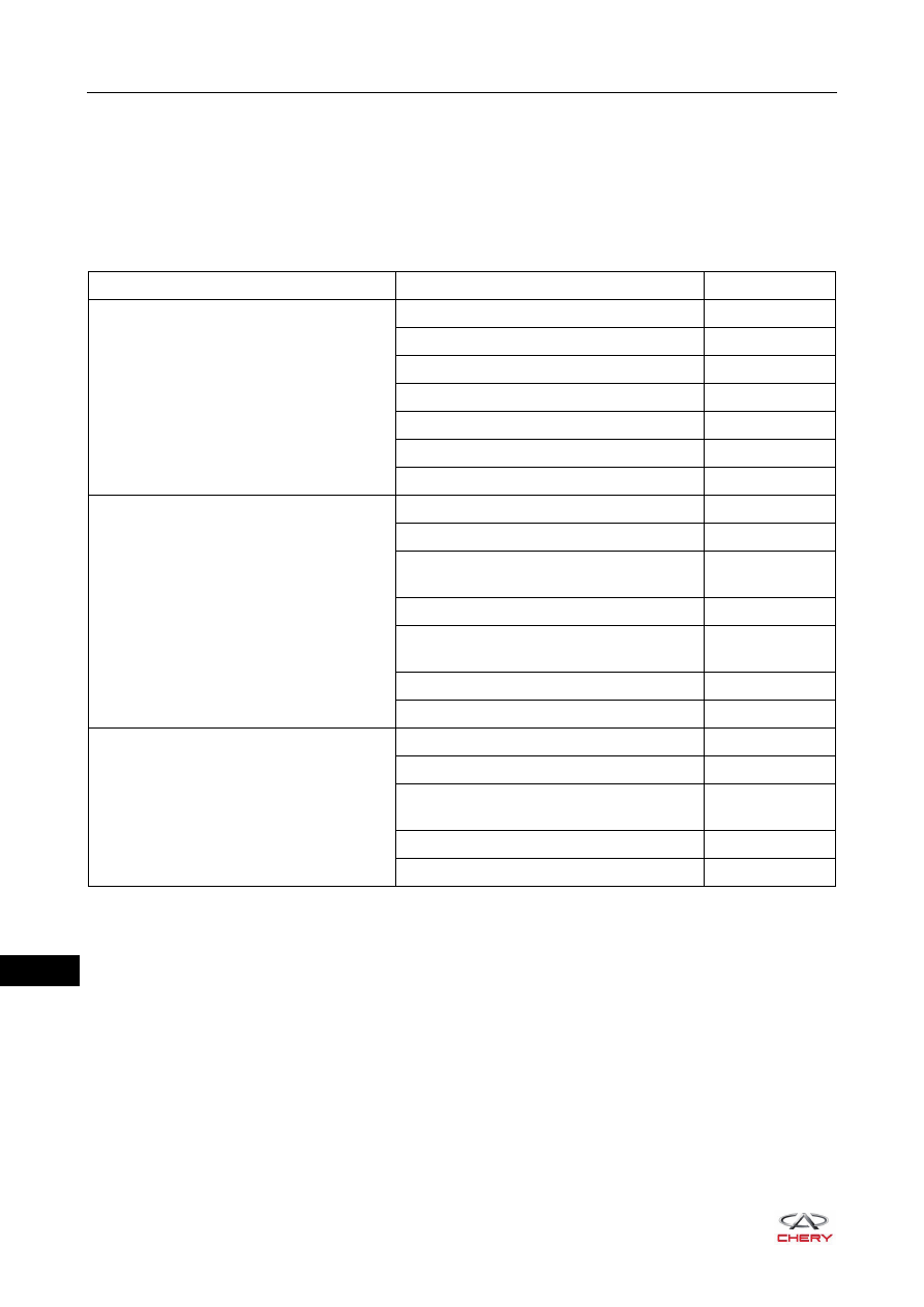
Problem Symptoms Table

HINT:
Use the table below to help determine the cause of problem symptoms. Check each suspected area in 
sequence. Repair or replace the faulty components, or adjust as necessary.

Symptom

Suspected Area

See page

Pulls

Tire (worn or improperly inflated)

24-7

Front wheel alignment (wrong)

23-50

Rear wheel alignment (wrong)

23-52

Front hub bearing (loose or worn)

22-9

Rear hub bearing (loose or worn)

22-19

Steering gear (misaligned or damaged)

29-23

Suspension component (worn)

23-12

Front wheel shimmy

Tire (worn or improperly inflated)

24-7

Wheel (imbalanced)

24-10

Front shock absorber assembly (stuck or 
damaged)

23-12

Front wheel alignment (wrong)

23-50

Control arm assembly ball pin (stuck or 
damaged)

23-22

Front hub bearing (loose or worn)

22-9

Steering gear (misaligned or damaged)

29-23

Rear wheel shimmy

Tire (worn or improperly inflated)

24-7

Wheel (imbalanced)

24-10

Rear shock absorber assembly (stuck or 
damaged)

23-29

Rear hub bearing (loose or worn)

22-19

Rear wheel alignment (wrong)

23-52

22–

9

22

ON-VEHICLE SERVICE

Front Hub Assembly

Removal

HINT:

 Use the same procedures for the right side and left side. 

 Procedures listed below are for the left side. 
1. Remove the front left wheel (

See page 24-9

).

2. Remove the front drive shaft assembly locking nut.

a. Using a nut chisel and a hammer, loosen the staked 

part of nut.

b. Remove the front drive shaft assembly locking nut 

(arrow) while applying the brakes securely.

(Tightening torque: 300 ± 20 N·m)

WARNING

 Be sure to wear necessary safety equipment to prevent accidents. 
 Check if safety lock of lifter is locked when repairing chassis parts.
 It is not permitted to weld or modify bearing parts of wheel suspension and guide parts of wheel.
 When removing chassis parts, replace the self-locking nuts and rusted nuts for safety.

RT21220050

CAUTION

 Loosen staked part of nut completely, otherwise it will damage the thread of drive shaft assembly.

RT21220060

22–

10

22

3. Remove the front left brake caliper assembly (

See page 26-28

).

4. Remove the front left brake disc (

See page 26-28

).

5. Remove the front left hub assembly.

a. Remove 4 coupling bolts (arrow) between front left hub 

assembly and front left steering knuckle assembly.

(Tightening torque: 70 - 75 N·m)

b. Remove the front left mudguard (arrow) and front left 

hub assembly (1).

6. Remove the front left hub bearing.

a. Place front left hub assembly on a hydraulic press, 

install bearing remover and adapter, and press out the 
front left hub with hydraulic press.

CAUTION

 Place front brake caliper assembly to a proper position after removal. Be careful not to extend front brake 

hose excessively.

RT21220070

1

RT21220080

RT21220090

22–

11

22

b. Remove the front left hub bearing.

Installation

Installation is in the reverse order of removal.

RT21220100

CAUTION

 Always tighten coupling bolts and nut to the specified torque.
 Check that hub assembly turns freely without sticking after installation. 


Content   ..  246  247  248  249   ..