Chery Tiggo 5 (T21). Manual - part 239


  Index      Chery     Chery Tiggo 5 (T21) - service repair manual 2014 year


Search            


Content   ..  237  238  239  240   ..


Chery Tiggo 5 (T21). Manual - part 239


19–

11

19

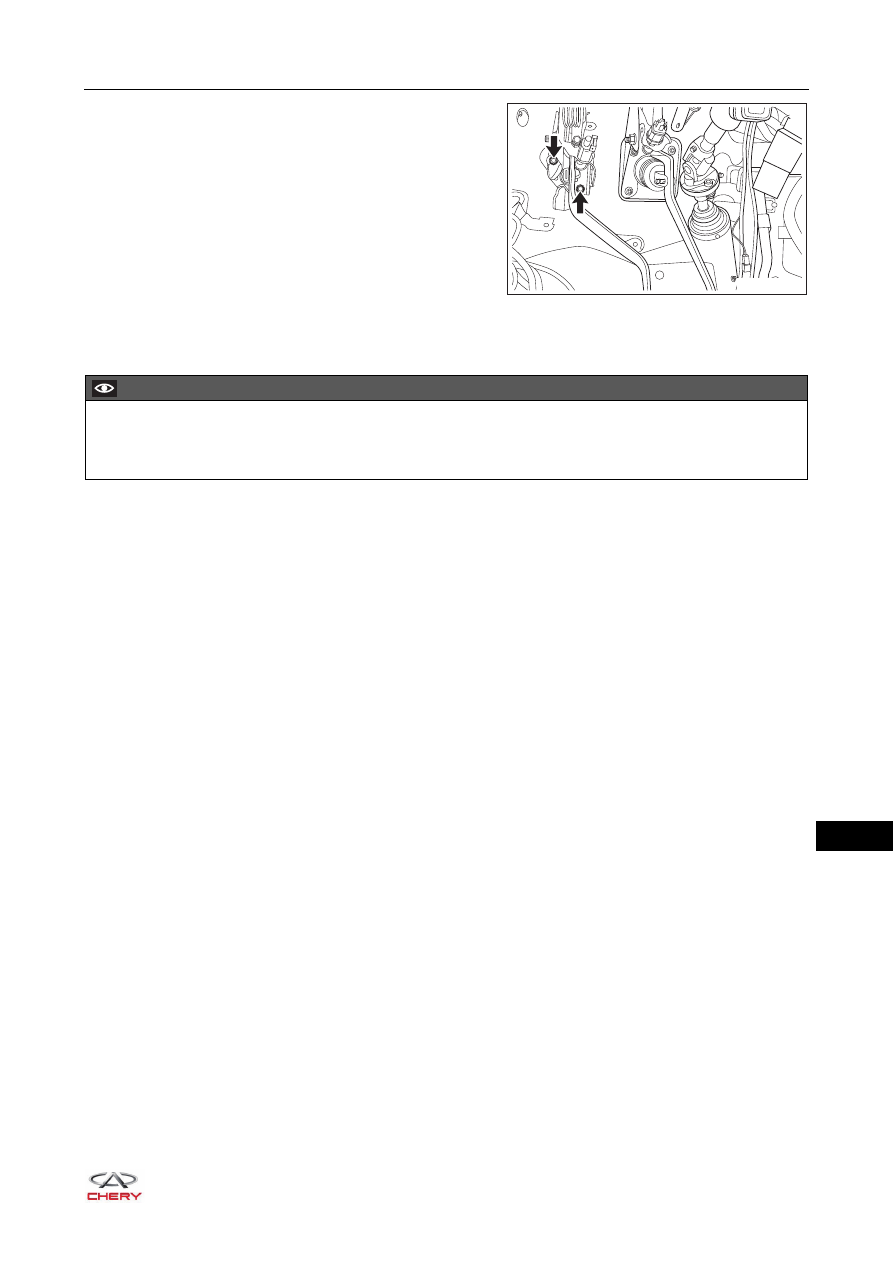
c. Remove 2 fixing nuts (arrow) from clutch master 

cylinder.

(Tightening torque: 25 ± 2 N·m)

Installation

Installation is in the reverse order of removal.

RT21190110

CAUTION

 Add brake fluid to "MAX".
 Perform bleeding procedure for hydraulic clutch and check brake fluid for leakage after installation.

19–

12

19

Clutch Release Cylinder Assembly

Removal

1. Disconnect the negative battery cable.
2. Drain the brake fluid (

See page 26-13

).

HINT:
Collect brake fluid with a container.

3. Remove the clutch release cylinder.

a. Remove the pipe joint and pipe assembly II from 

clutch release cylinder.

(Tightening torque: 16 ± 2 N·m)

b. Remove the clutch release cylinder fixing bolts (arrow) 

and then remove the clutch release cylinder.

(Tightening torque: 22 ± 2 N·m)

WARNING

 Brake fluid in release cylinder is harmful to your skin, be sure to wear protective gloves before operation.
 Once brake fluid contacts with your skin, wash it off with water immediately.

CAUTION

 Collect brake fluid with a container while servicing.
 Make sure fluid level in reservoir is at "MAX" after replacing release cylinder.
 DO NOT allow brake fluid to spray onto body surface, or it will damage the painted surfaces. If any brake 

fluid is get onto the painted surfaces, wash it off with water immediately.

RT21190150

RT21190160

19–

13

19

Installation

Installation is in the reverse order of removal.

CAUTION

 Add brake fluid to "MAX".
 Connect pipe joint of pipe assembly II to the clutch release cylinder assembly first, then tighten it after 

installation.

 Be sure to align the push rod of clutch release cylinder assembly with hole in transmission case release 

fork, and tighten bolts to specified torque.

 Perform bleeding procedure for hydraulic clutch and check system line for leakage after installation.

19–

14

19

Clutch Unit

Removal

1. Remove the transmission assembly (

See page 17-21

).

2. Remove the clutch release bearing (1).
3. Remove the release fork (2) from clutch cover.

4. Remove the release fork ball seat (1).
5. Remove the release fork dust boot (2).

6. Remove the clutch pressure plate bolts.
7. Remove the clutch pressure plate and clutch driven disc.

Inspection

1. Check clutch driven disc.

a. Visually check clutch driven disc for dirt or glazing. Clean or replace clutch driven disc as necessary.

2. Use a vernier caliper to measure the thickness of clutch 

driven disc.
Standard thickness: 7.6 ± 0.2 mm
Minimum rivet depth: 1.2 mm
If result is not as specified, replace clutch driven disc.

1

2

RT21190170

1

2

RT21190180

RT21190190

1

3

5

6

4

2

RT21190200


Content   ..  237  238  239  240   ..