Chery Tiggo 5 (T21). Manual - part 235


  Index      Chery     Chery Tiggo 5 (T21) - service repair manual 2014 year


Search            


Content   ..  233  234  235  236   ..


Chery Tiggo 5 (T21). Manual - part 235


18–

129

18

TCU

Removal

1. Turn off all the electrical devices and ignition switch.
2. Disconnect the negative battery cable.
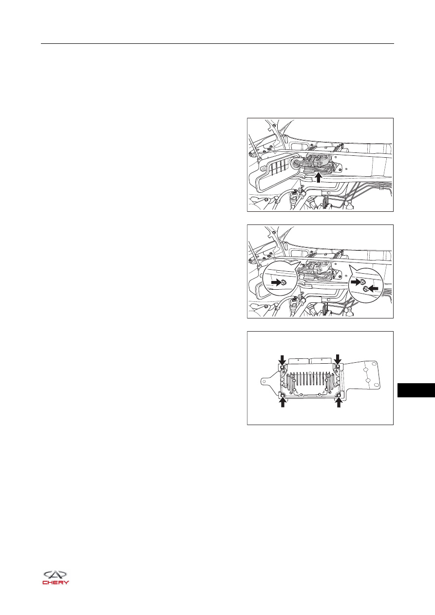
3. Remove the TCU and ECM connector protective cover.
4. Disconnect the TCU and ECM connector.

5. Remove the TCU mounting bracket.

6. Remove the TCU fixing bolts (arrow). 

(Tightening torque: 6 - 8 N·m)

Installation

Installation is in the reverse order of removal.

RT21180621

RT21180620

RT21180630

18–

130

18

CVT Assembly

Removal

1. Apply the parking brake.
2. Turn off all the electrical devices and ignition switch.
3. Disconnect the negative battery cable.
4. Drain the automatic transmission fluid (

See page 18-110

).

5. Remove the air filter (

See page 10-17

).

6. Remove the battery (

See page 16-7

).

7. Remove the battery tray (

See page 16-9

).

8. Remove the starter (

See page 15-64

).

9. Remove the engine speed sensor (

See page 06-249

).

10.Disconnect the primary shaft pressure sensor wire 

harness connector (arrow).

11.Disconnect the wire harness connectors on the 

transmission:
 Transmission range sensor connector;
 Transmission solenoid wire harness connector;
 Turbine speed sensor wire harness connector;
 Primary shaft speed sensor wire harness connector;
 Remove the transmission ground wire harness fixing 

bolt;

(Tightening torque: 18 - 22 N·m)

CAUTION

 In the removal and installation of transmission, make sure that the torque converter does not drop from 

the transmission.

 Do not scratch or damage the parts in the removal and installation.

RT21180640

RT21180650

18–

131

18

 Secondary shaft pressure sensor wire harness 

connector;

 Secondary shaft speed sensor wire harness 

connector.

12.Disconnect the connection of the gear shift cable on the transmission (

See page 18-127

).

13.Remove the transmission fluid coolant hose clamps 

(arrow) and detach the hoses.

14.Use engine equalizer to fix the engine assembly.
15.Remove the engine front, rear and left mountings (

See page 07-64

).

16.Remove the bolts connected with the engine at the upper 

part of the transmission. 

(Tightening torque: 75 - 85 N·m)

17.Raise the vehicle with a lifter.

RT21180660

RT21180670

RT21180680

RT21180690

18–

132

18

18.Remove the dust baffle fixing bolts, and take out the dust 

baffle. 

(Tightening torque: 45 - 55 N·m)

19.Turn the crankshaft and turn the connecting bolt of 

flywheel and torque converter to the middle section of U 
slot to lock the crankshaft bolts. Remove 4 connecting 
bolts of the flywheel and torque converter. 

(Tightening torque: 50 - 60 N·m)

HINT:
The crankshaft should rotate clockwise viewing from the 
front of the engine.

20.Remove the axle shaft.
21.Use transmission carrier (1) to support the transmission 

(2).

22.Remove the transmission and engine front connecting 

bolt (1).

(Tightening torque: 75 - 85 N·m)

RT21180700

RT21180710

2

1

RT21180720

RT21180730


Content   ..  233  234  235  236   ..