Chery Tiggo 5 (T21). Manual - part 222
18–
77
18
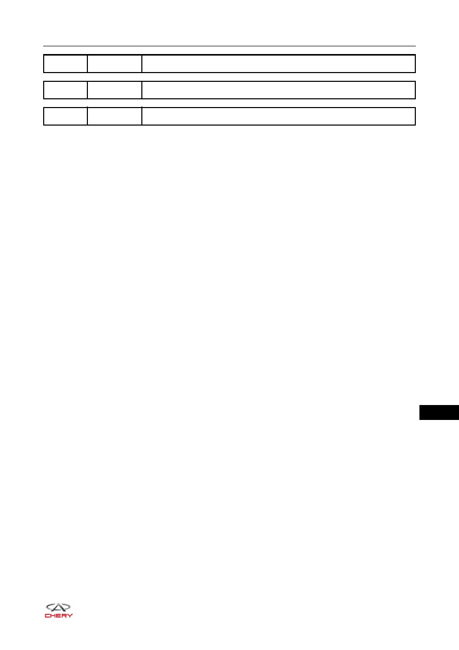
DTC
P0900
Clutch Actuator Circuit Open
DTC
P0902
Clutch Actuator Circuit Low
DTC
P0903
Clutch Actuator Circuit High
|
|
|
18– 77 18 DTC P0900 Clutch Actuator Circuit Open DTC P0902 Clutch Actuator Circuit Low DTC P0903 Clutch Actuator Circuit High |