Chery Tiggo 5 (T21). Manual - part 68
06–
114
06
a. Remove knock sensor.
b. Check installation area of knock sensor, and check for damage, foreign matter and excessive movement,
etc. that cause signal incorrectness.
a. Check resistance between knock sensor terminals 1 and 2.
OK: 4.9 ± 20% MΩ (at normal temperature)
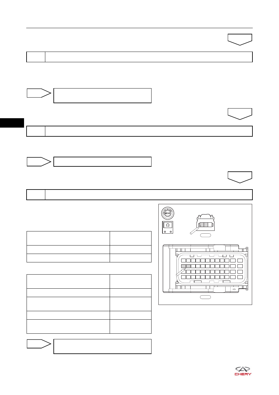
a. Disconnect ECM wire harness connector E-035.
b. Check wire harness between terminals of connector E-035
and connector E-005.
Check for Open
Check for Short
3
Check installation of knock sensor
OK
Clean installation area or replace knock
sensor
NG
4
Check resistance of knock sensor
OK
Replace knock sensor
NG
5
Check knock sensor signal circuit
OK
E-035
E-005
37 38 39 40 41 42 43 44 45 46
47
48
25 26 27 28 29 30 31 32 33 34
35
36
13 14 15 16 17 18 19 20 21 22
23
24
1
2
3
4
5
6
7
8
9 10
11
12
1 2 3
-
+
RT21065043
Multimeter Connection
Specified
Condition
E-035 (26) - E-005 (1)
Continuity
E-035 (25) - E-005 (2)
Continuity
Multimeter Connection
Specified
Condition
E-035 (26) or E-005 (1) - Body ground
No continuity
E-035 (26) or E-005 (1) - Battery
positive
No continuity
E-035 (25) or E-005 (2) - Body ground
No continuity
E-035 (25) or E-005 (2) - Battery
positive
No continuity
Replace wire harness or connector (knock
sensor - ECM)
NG