Chery Tiggo 5 (T21). Manual - part 67


  Index      Chery     Chery Tiggo 5 (T21) - service repair manual 2014 year


Search            


Content   ..  65  66  67  68   ..


Chery Tiggo 5 (T21). Manual - part 67


06–

110

06

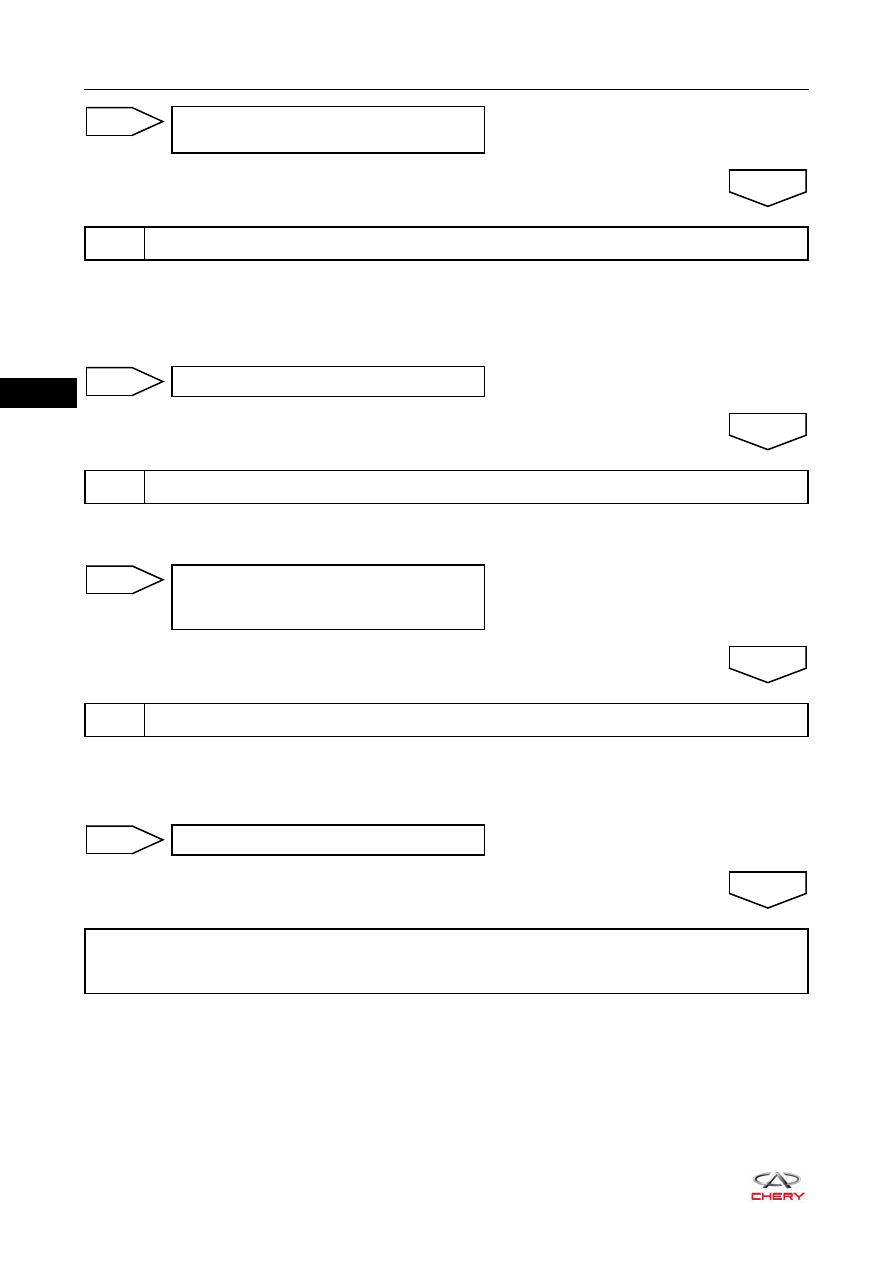
a. Install a normal engine speed sensor.
b. Connect engine speed sensor connector.
c. Turn ignition switch to ON, start the engine and observe the signal waveform of the engine speed sensor 

with an oscilloscope.

a. Turn crankshaft, and check crankshaft and flywheel gear ring for damage and foreign matter, etc. that 

cause signal incorrectness.

a. Use X-431 3G diagnostic tester to read the ECM DTC. 
b. Refer to "DTC Confirmation Procedure".
c. Check if DTC P0322-00 still exists.

Replace wire harness or connector 
(engine speed sensor - ECM)

NG

7

Install a normal engine speed sensor and observe signal waveform

OK

Replace engine speed sensor

OK

8

Check flywheel gear ring

NG

Clear off debris and clean flywheel gear 
ring. Replace flywheel if necessary 

(

See page 07-42

)

NG

9

Check for DTCs

OK

Replace ECM

NG

System is operating normally.
Reassemble vehicle and perform a road test to confirm that malfunction reported by customer has 
been repaired.

OK

06–

111

06

DTC

P0327-00 Knock Sensor 1 Circ. Low Input

DTC

P0328-00 Knock Sensor 1 Circ. High Input

06–

112

06

ET21065011

1

2

1-26

1-25

GY

WY

GY

WY

KNOCK
SENSOR

2

1

E-007
E-038

1 2 3

B

E-005

E-005

ECM-2

ECM-1

E-033

E-035

2-63

2-64

1-47

Br

Br

B

B

Br

B

1-48

E-026

E-028

37 38 39 40 41 42 43 44 45 46

47

48

25 26 27 28 29 30 31 32 33 34

35

36

13 14 15 16 17 18 19 20 21 22

23

24

1

2

3

4

5

6

7

8

9 10

11

12

B

E-033

B

E-035

49 50 51

63

64

15

16

31

32

47

48

33 34 35

17 18 19

1

2

3

52 53 54 55 56 57 58 59 60 61 62

36 37 38 39 40 41 42 43 44 45 46

20 21 22 23 24 25 26 27 28 29 30

4

5

6

7

8

9 10 11 12 13 14

1

2

3

4

5

6

7

8

9

10

11

12

13

14

15

16

17

18

19

20

21

22

23

24

25

26

31

35

39

40

41

42

32

33

36

37

38 34

27

28

29

30

B

E-007

06–

113

06

DTC Confirmation Procedure

Confirm that battery voltage is over 12 V before performing the following procedures.
 Turn ignition switch to LOCK.
 Connect X-431 3G diagnostic tester (the latest software) to Data Link Connector (DLC).
 Turn ignition switch to ON.
 Use X-431 3G diagnostic tester to record and clear the DTCs stored in the ECM.
 Start the engine and warm it up to normal operating temperature, and then select Read Code.
 If the DTC is detected, the malfunction indicated by the DTC is current. Go to the diagnosis 

procedure - Step 1.

 If DTC is not detected, the malfunction indicated by the DTC is intermittent (

See page 06-18

).

Diagnosis Procedure

a. Turn ignition switch to LOCK.
b. Check ECM grounds E-026 and E-028 (

See page 06-18

). 

a. Disconnect knock sensor connector E-005.
b. Check knock sensor connector.

DTC Code

DTC Definitions

DTC Detection 

Conditions

Possible Cause

P0327-00

Knock Sensor 1 Circ. 
Low Input

Engine running

 Knock sensor
 Wire harness or connector
 ECM

P0328-00

Knock Sensor 1 Circ. 
High Input

CAUTION

 When performing circuit diagnosis and test, always refer to the circuit diagram for specific circuit and 

component information.

1

Check ECM ground point

Repair or replace ground wire harness or 
ground point

NG

2

Check knock sensor connector

OK

RT21060330

Repair or replace connector

NG


Content   ..  65  66  67  68   ..