Chery Tiggo. Manual - part 96
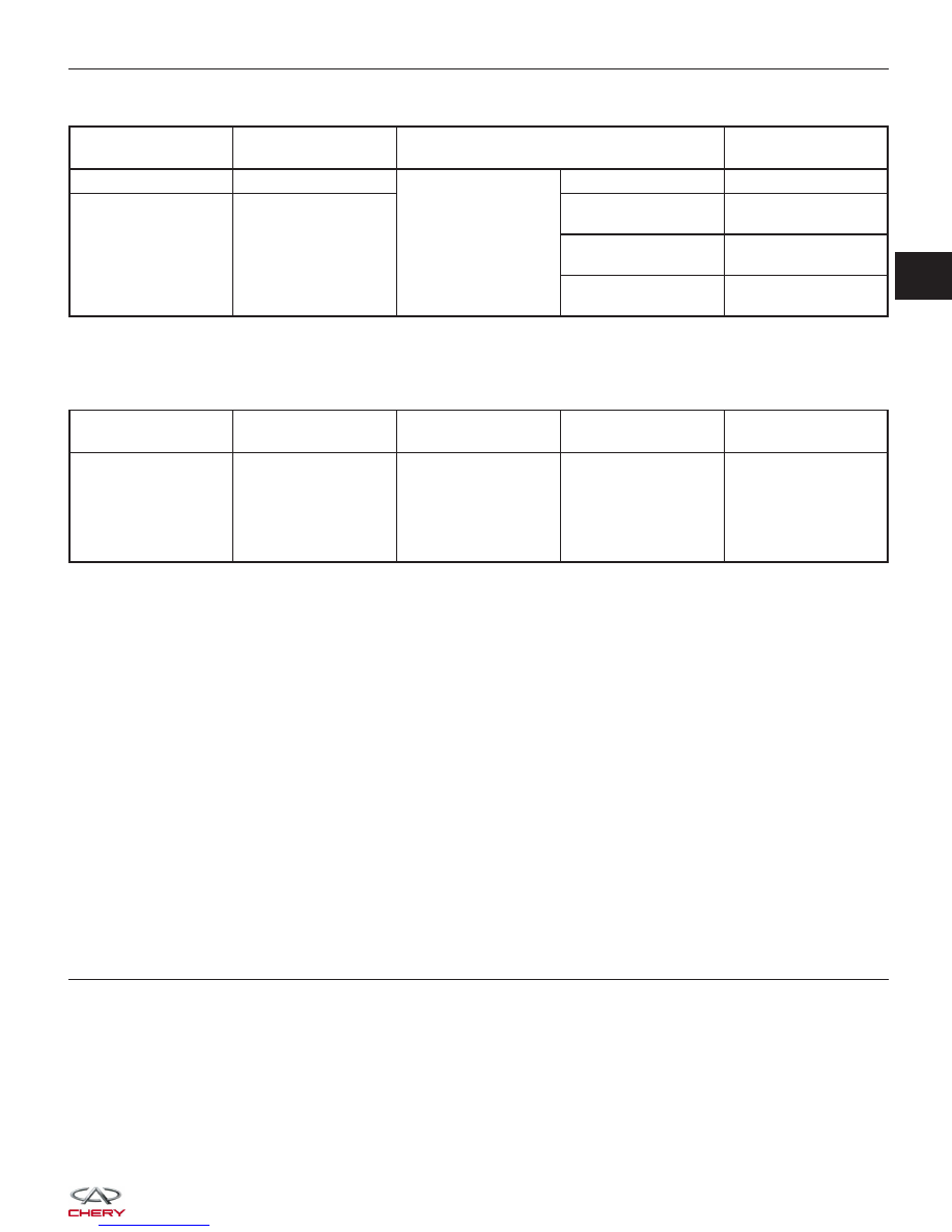
Check reference values between ECM terminals and ground under the following conditions:
ECM TERMINAL
NO.
ITEM
CONDITION
DATA (DC
VOLTAGE)
17
Sensor (GND)
Ignition switch on
-
Approximately 0 V
39
Engine Coolant
Temperature (ECT)
sensor
ECT: 59°C
Approximately
1.89 V
ECT: 78°C
Approximately
1.25 V
ECT: 90°C
Approximately
0.94 V
On Board Diagnostic Logic
• Self-diagnosis detection logic.
DTC NO.
DTC DEFINITION
DTC DETECTION
CONDITION
DTC SET
CONDITION
POSSIBLE CAUSE
P0118
Engine coolant
temperature circuit
high input
• Ignition switch:
ON
• Engine: Running
Signal output is
above maximum
acceptable range for
a few seconds
continuously.
• ECT
• Harness or
connectors (The
sensor circuit is open
or shorted)
• ECM
DTC Confirmation Procedure:
Before performing the following procedure, confirm that battery voltage is more than 12 V.
• Turn ignition switch off.
• Connect the X-431 scan tool to the Data Link Connector (DLC) - use the most current software available.
• Turn ignition switch on.
• With the scan tool, record and erase stored DTCs in the ECM.
• Start engine and warm it to normal operating temperature, then select view DTC and data stream.
• If the DTC is detected, the DTC condition is current. Go to Diagnostic Procedure - Step 1.
• If the DTC is not detected, the DTC condition is intermittent (See Diagnostic Help and Intermittent DTC Trou-
bleshooting in Section 03 Electronic Engine Controls for more information.
NOTE :
• Before performing this DTC diagnostic procedure, verify that the Engine coolant temperature is normal.
NOTE :
While performing electrical diagnosis & testing, always refer to the electrical schematics for specific circuit
and component information.
Diagnostic Procedure
1.
CHECK GROUND CONNECTIONS
• Turn ignition switch off.
• Loosen and retighten ground screws on the body (See Ground Inspection in Section 03 Electronic Engine Con-
trols).
• Inspect ground connections E-207 and E-208 mounting position (See Vehicle Wiring Harness Layout - Engine
Room Harness (With 1.6L/1.8L Engine) in Section 16 Wiring).
Are the ground connections OK?
Yes
>>
Go to the next step.
No
>>
Repair or replace ground connections.
DIAGNOSIS & TESTING
03