Chery Fora (Elara A520). Manual - part 118


  Index      Chery     Chery Fora (Elara A520) - service repair manual


Search            


Content   ..  116  117  118  119   ..


Chery Fora (Elara A520). Manual - part 118


  CHERY A520 SERVICE MANUAL                                                        CHASSIS 

59 


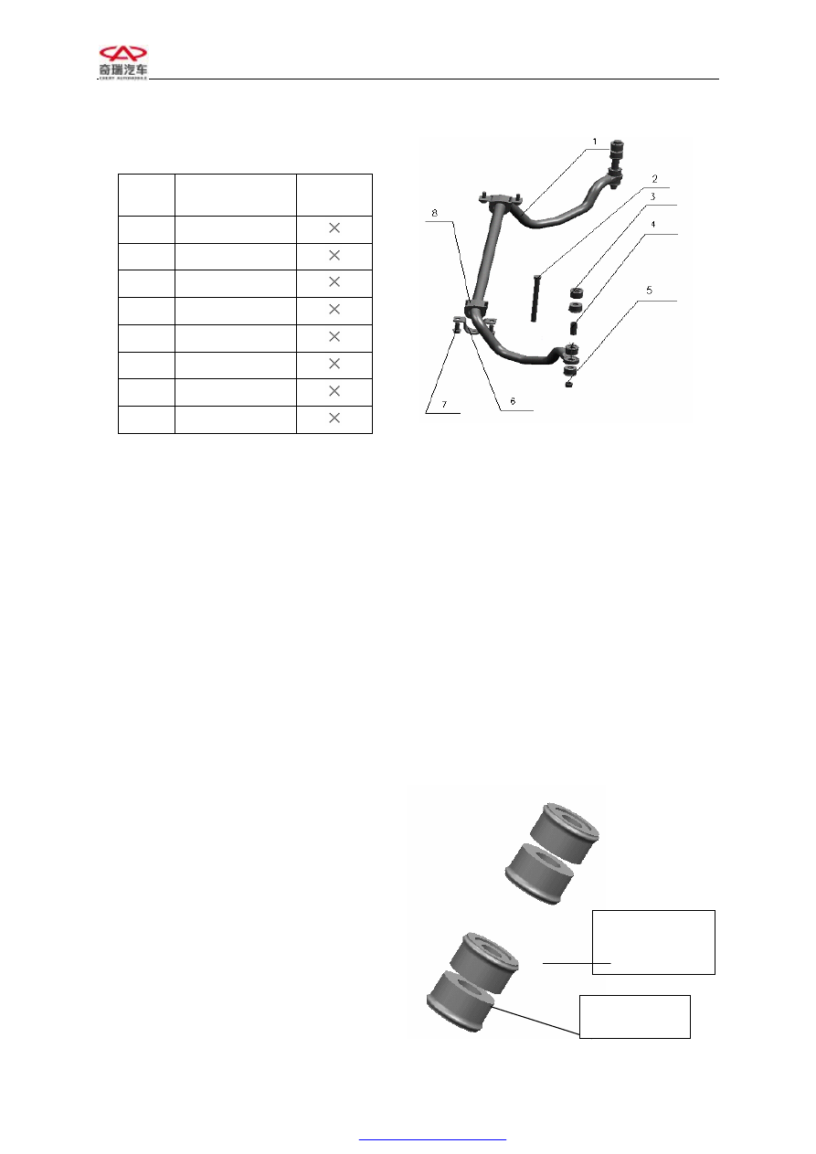
VI.  MOUNTING  OF  THE  FRONT 
STABILIZER BAR ASSEMBLY 

Serial 

No. 

Name of Spare 

Parts 

Quantity 

Stabilizer bar 

1

Extension bolt 

1

Rubber pad 

1

Metal sleeve 

1

Nut 

1

Clamp 

1

Bolt 

1

Rubber support 

1


Put  the  rubber  support  sheath  8  onto  the 
stabilizer  bar1,  install  the  clip  6  onto  the 
rubber  support  sheath  8,  and  fix  the  central 
part  of  the  entire  stabilizer  bar  assembly 
onto the under-frame by use of bolt 7 with a 
specified torque of 25±2m. The both ends of 
stabilizer  bar  connect  to  the  lower  control 
arm  through  an  extension  bolt  with  a 
specified  torque  of  50±3m.  The  top  and 
bottom  surfaces  of  the  connection  joint  of 
stabilizer  bar  end  and  lower  control  arm 
have  a  rubber  pad  3  respectively,  and  there 
is  a  metal  sleeve  4  between  the  second  and 
third  rubber  pads  of  either  end  of  stabilizer 
bar.   


It  is  to  be  noted  that  all  the  rubber  pads  3 
are  the  same,  but  the  top  and  bottom  sides 
of  each  rubber  pad  are  different,  of  which 
one side has a sulfurate metal pad, while the 
other  has  no  such  a  metal  pad.  Thus,  the 
each  end  of  four  rubber  pads  has  obverse 
and  reverse  surfaces  in  the  case  of 
assembly.   

Note:  The  four  rubber  pads  of  each  end  of 
the  stabilizer  bar  must  be  mounted 
according  to  the  sequence  illustrated  in  the 
figure.   


The Side That Has A 

Sulfurate Metal Pad 

The Side That Has 

No Metal Pad 

  CHERY A520 SERVICE MANUAL                                                        CHASSIS 

60 

VII. ASSEMBLY OF FRONT AXLE AND FRONT SUSPENSION


1    Nut

2    Nut

3 Bolt

4 Nut

8 Nut

14 Nut 

13    Clip

16    Bolt 

15 Bolt 


5 Bolt 

6 Sleeve

10 Bolt

11 Bolt 

9 Nut 1 

12 Rubber Support 

21 Antiroll Bar 

22 Engine Side Member 

17 Front Sliding Pole 

18 

Steering 

Knuckle 

19Control Arm 

20 Under-frame 

23 Bolt

24    Nut 

7 Rubber Cushion 

  CHERY A520 SERVICE MANUAL                                                        CHASSIS 

61 

——

Use  bolt  23  to  connect  the  control  arm  assembly19  and  under-frame  20  up  to  the 

specified fastening torque (bolt 23:180±15Nm). The left and right sides are the same. 


——

Use  bolt  14  and  installation  clamp  of  stabilizer bar  13 to  fix  the  stabilizer bar  assembly 

21 onto the rubber sleeve 12 up to specified fastening torque of 25±2 Nm. The left and right 
sides are the same 

——

Use bolt 5, stabilizer bar rubber pad7, metal sleeve 6 and nut 8 to fix the end of stabilizer 

bar assembly 21 onto the control arm19 up to specified fastening torque of 50±3Nm. The left 
and right sides are the same. 

——

Use nut 24 to connect the strut assembly 17 with the vehicle body to specified torque of 

50±10 Nm. The left and right sides are the same. 

——

Use bolt 1, nut 2 to connect the strut assembly 17 with the steering knuckle 18 up to the 

specified fastening torque of 110±5Nm. The left and right sides are the same. 

——

Use nut9, bolt 10 and bolt 11 to connect the under-frame assembly 20 and  vehicle  body 

up to specified  fastening  torque  (nut  9:  180±15  Nm,  bolt  10:  80  -90  Nm,  bolt  11:  180±15 
Nm). The left and right sides are the same. 

——

Use bolt3 and nut 4 to connect the control arm19, steering knuckle18 and front strut up to 

specified fastening torque of 110±5Nm. The left and right sides are the same. 

  CHERY A520 SERVICE MANUAL                                                        CHASSIS 

62 

SECTION II REAR SUSPENSION 

STRUCTURE FEATURE 

Adopt  longitudinal  trailing  arm  suspension,  three-linkage  rod,  cylindrical  coil  spring, 
double-acting telescopic vibration damper. 

One  end  of  longitudinal  rear  trailing  arm  connects  with  vehicle  body  through  rubber  hinge. 
This  rubber  hinge  has  different  longitudinal  rigidity.  One  end  of  the  three  horizontal 
oscillating arms connects with rear trailing arm by use of rubber bushing, while the other end 
connects  with  vehicle  body  through  rubber  bushing.  The  guide  bar,  rear  lower  oscillating 
arms  connects  with  vehicle  body  through  eccentric  adjusting  bolts.  By  adjusting  the  two 
eccentric  adjusting  bolts,  we  can  regulate  the  rear  wheel  toe-in  and  camber  angle.  The 
three-linkage  mechanism  can  facilitate  the  rear-wheel  alignment  parameters  to  generate 
smaller change and to have better operating stability.   

The lower part of strut connects with rear lower control arm by use of rubber hinge, while the 
upper  part  directly  connects  with  vehicle  body  through  rubber  cushion.  The  rubber  cushion 
can not only isolate a portion of noise, but can also damp the vibration passing from the road. 
As a result, the upper part of strut is fixed onto the vehicle body and moves slightly. However, 
the lower part of strut shall bounces up and down simultaneously with the rear lower control 
arm.  Compared  with  non-independent  suspension,  this  vibration  damper  shall  bear  a  minor 
side  force.  The  middle  part of  strut  connects with coil spring  as  well  as damping  block  and 
bearing parts.     

A minor unsprung mass; the suspension occupies a small space; elastic components only bear 
vertical force, thus spring with smaller rigidity can be used to reduce the vibration frequency 
of  car  and  improve  the  smoothness  of  car  driving;  the  left  and  right  wheels  move 
independently  without  influence  on  each  other,  which  can  not  only  reduce  inclination  and 
vibration of vehicle body, but can also boast a good surface adhesion on the bumpy road.   


Content   ..  116  117  118  119   ..