Chery A15 / 480 LHD model. Manual - part 71
Speed sensor
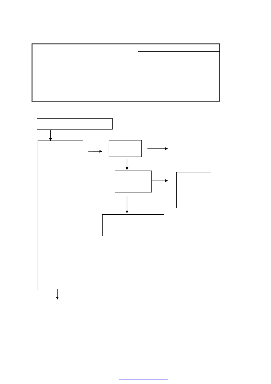
Possible Cause
4. The DTCs are 00283, 00285, 00290, 00287
[Description] The DTCs will appear when the
sensor has the recognizable open circuit,
short circuit and other failures.
[Hint] It may be caused due to the poor contact of
sensor, the short circuit of coil or harness,
or the failure of sensor signal processing
circuit in the ABS ECU.
· Open circuit of sensor connector
· Short circuit of sensor
· Short circuit between the sensor
connection or harness with the
counter-earth or power supply
· ABS ECU sensor signal processing
circuit failure
Check the sensor of any wheel
Normal
Abnormal
No
Yes
Normal
Replace ABS ECU
Remove the ABS
ECU connector, and
check whether the
resistances between
the following
terminals of ABS
ECU conform to the
standard values?
Standard value: 1.0
to 1.3 kΩ
Measure the
resistances, and, at
the same time,
swing the sensor
harness and
connector.
MK20I/E
FL: 1 to 2
FR: 19 to 20
RL: 5 to 6
RR: 22 to 23
Check the
related sensor
connector
The
failure
reoccurs or not?
Refer to the
“Repair
Details
of
Random
Failure”
Check
the
electrical
wirbetween the ABS ECU
and sensores
Repair the connector
Normal