Chery A15. Manual - part 147


  Index      Chery     Chery A15 - service repair manual


Search            


Content   ..  145  146  147  148   ..


Chery A15. Manual - part 147


1-Electronic leakage detector      2-Power plug   3-

Detecting head 

In case of leakage at cooling pipeline connector, replace the O-ring. 

(II). Soapy Water 

Apply soapy water on suspect leaking area. Soap water will bubble in case of coolant leakage. 

(III). Halogen Detector Lamp 

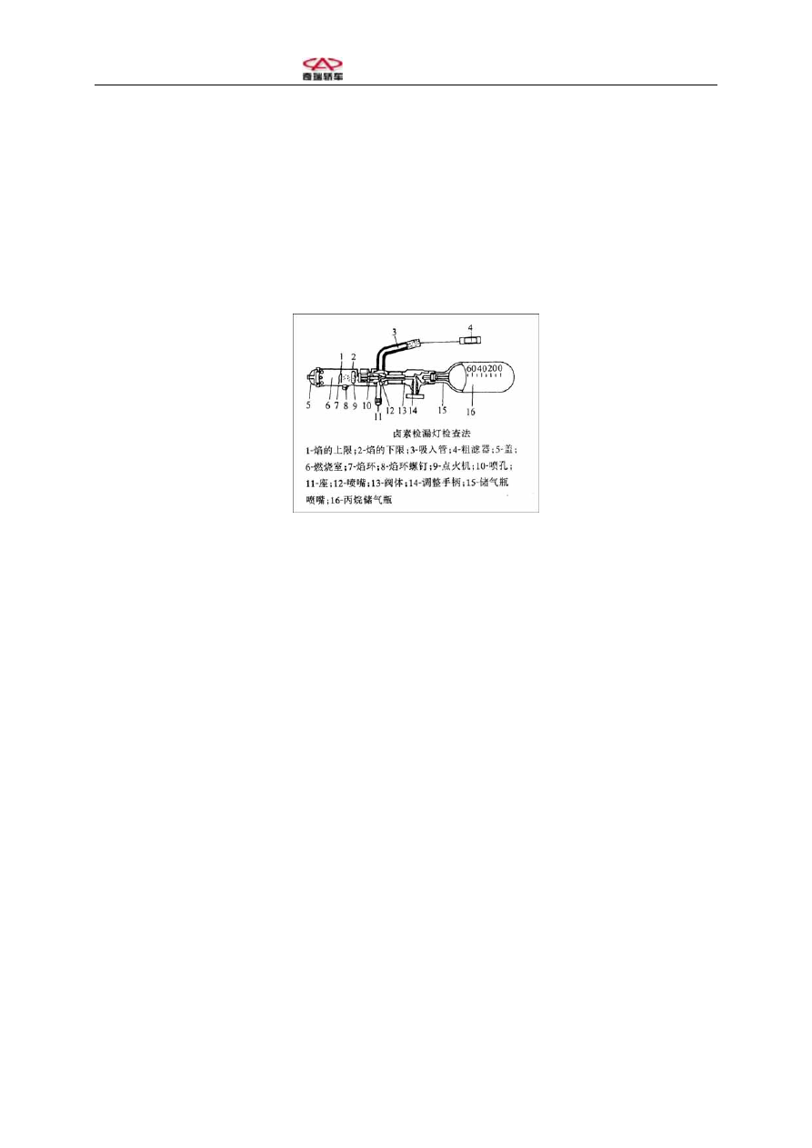
Halogen detector lamp is a propane combusting blowlamp as shown in the figure. 


Inspection using halogen detector lamp 

1. Upper flame limit    2. Lower flame limit    3. Suction tube  4. Strainer filter  5. Cover  6. Combustion chamber 

7. Flame ring    8. Flame ring screw    9. Lighter    10. Nozzle hole  11. Base  12. Nozzle  13. Valve 

14. Adjusting handle    15. Gas tank nozzle    16. Propane gas tank 

Operating steps of halogen detector lamp: 

(1). Check liquid propane volume in the bomb-like gas tank. 

(2). Tighten gas tank (propane tank) 16 at the lower end of detector lamp body. 

(3). Insert an alight match into the detector lamp lighter 9, and turn counterclockwise the 

adjusting handle 14 slowly until detector lamp is lighted. 

(4). Adjust to minimize the flame, for smaller flame is more sensitive to leakage. 

(5). Make fore end of suction tube 3 approach suspect leaking areas. 

(6). Observe changes in flame color. Flame is almost colorless when there is no leakage, and 

will turn light green with small leakage, light blue with larger leakage and purple with 

extremely large leakage. 


Section Thirteen: Filling of Cooling Oil 


Cooling oil may be added by direct filling or vacuum suction. 


I. Direct Filling 

Remove filling plug and fill in cooling oil of specified model. 


II. Vacuum Suction 

Vacuumize cooling system to 30psi, then fill in cooling oil as per following steps: 


低压表 

Low pressure gauge 

排气口 Vent 

高压表 

High pressure gauge 

辅助阀 Auxiliary 

valve 

低压手动阀门 

Low pressure manual valve 

真空泵 Vacuum 

pump 

高压手动阀门 

High pressure manual valve 

高压侧软管 

High pressure side hose 

低压侧软管 

Low pressure side hose 

高压管路 

High pressure pipe 

回气口 

Air return inlet 

油杯 Oil 

cup 

抽真空加注冷冻机油 

Vacuumize to add cooling engine oil 

(1). Shut high pressure manual valve and auxiliary valve. 

(2) Demount high pressure side hose from manifold pressure gauge, and dip one end into oil 

cup. 

(3). Open auxiliary valve to suck cooling oil in oil cup into cooling system. 

(4). Shut auxiliary valve right before cooling oil in oil cup is sucked out to avoid air suction. 

(5). Tighten high pressure side hose connector on manifold pressure gauge, open high 

pressure manual valve and start vacuum pump to vacuumize high pressure hose. Reopen 

auxiliary valve to vacuumize system to 30psi, and then keep vacuumizing for an additional 15 

minutes to exhaust air sucked into system with oil. The cooling oil is now at high pressure 

side, and will return to compressor after the system is working. 


III. Cooling Oil Model and Adding Volume 

Model: SP10, 150ml. 

Cooling oil shall be added when repairing parts or a certain mileage is reached. Oil volume 

may be checked through oil level in compressor. Required adding volume when replacing 

parts: evaporator and condenser: 30ml; dryer: 20ml; pipeline: 10ml. 


Section Fourteen: Vacuumization of Air Conditioning System   


Vacuumization dose not drain water out of system, but lowers boiling point of water after 

there is vacuum in the cooling system, thus the water is boiled at a lower temperature and 

exhausted from the system in the form of steam. 

Perform leakage detection before vacuumization, for it will be difficult to identify leakage, if 

any, after the system is vacuumized. 

The purpose of vacuumizing the system is to further check the airtightness of cooling system 

under vacuum condition, and make preparation for filling of cooling oil. Vacuumizing steps: 

(1). Connect high pressure gauge hose with high pressure maintenance valve on coolant tank, 

and connect low pressure gauge hose to low pressure maintenance valve on compressor 

through evaporator, and connect central hose with vacuum pump. 

(2). Open high, low pressure valves of manifold pressure gauge, and start vacuometer. 

(3). Keep vacuumizing for at least 15 minutes with vacuum pump to make vacuum reading of 

low pressure gauge lower than 30psi. If this value is not reached, shut manual valves at both 

high and low pressure sides and stop vacuumizing to detect leakage. 

(4). Shut valves, and the gauge reading shall not increase within 10 minutes. This is so-called 

“vacuum leak test”. Any decrease in vaccum degree indicates leakage, in which case the 

leakage detector shall be used. 

(5). If no visible increase in gauge reading is seen in 10 miniutes, the system is ready for 

coolant filling. 

(6). Restart vacuum pump, open low pressure valve of manifold pressure gauge and continue 

to vacuumize for 15 minutes, then shut low pressure valve to finish vacuumizing and fill in 

coolant. 


低压:Low pressure    高压:High pressure    开:Open 

Vacuumization 

1-Hose connected to low pressure maintenance valve; 2-Hose connected to high pressure maintenance valve; 

3-Low pressure gauge; 4-High pressure gauge; 5-Low pressure manual valve; 6-High pressure manual valve; 

7-Vacuum pump 


Section Fifteen: Filling of Coolant 


I. Filling Precautions 

(1). Avoid skin contact with coolant. Wear rubber gloves and eye shield during operation. 

(2). Coolant must be operated in a well ventilated place. Coolant at room temperature is a 

colorless gas with a density higher than the air, and will accumulate on the ground in 

maintenance site and easily cause suffocation of operator. 

(3). Coolant is prohibited to contact with open flame, for poisonous gas will be generated. 

(4). O-ring is for one-time use and shall be thrown away after use. 

(5). The R134a coolant used by Chery A15 shall not be interchangeable with R12 coolant, and 

mixing of compressor oil is not allowed. Any tool that has contacted with one kind of coolant 

in operation is not allowed to contact with another. 


Content   ..  145  146  147  148   ..