BMW 3 (E46). Manual - part 239
600-3
Wiring Diagrams
The wiring diagrams shown in
Electrical Wiring Diagrams have been
specially designed to enable quick and
efficient diagnosis and troubleshooting
of electrical malfunctions.
Wiring codes and
abbreviations
A lot of information is included in each
wiring diagram if you know how to read
them. Wire colors in the diagrams are
abbreviated. Combined color codes
indicate a multi-colored wire. For
example the code BLU/RED indicates a
blue wire with a red stripe.
Many electrical components,
connectors, fuses, and ground
locations are identified using a unique
number. Each of these numbers
corresponds to a particular part in the
circuit commonly found in Electrical
Wiring Diagrams.
Note:
Sometimes the color of an installed
wire may be different than the one on
the wiring diagram. Don't be concerned.
Just be sure to confirm that the wire
connects to the proper terminals.
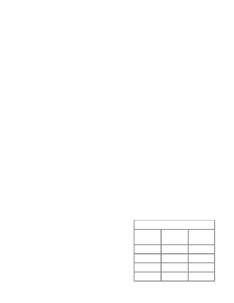
Table b. Wire color codes
German
code
English
code
Color
SW
BLK
Black
BL
BLU
Blue
BR
BRN
Brown
GN
GRN
Green