BMW 3 (E46). Manual - part 233


  Index      BMW     BMW 3 (E46) - service repair manual 2006 year


Search            


Content   ..  231  232  233  234   ..


BMW 3 (E46). Manual - part 233


The convertible top storage compartment
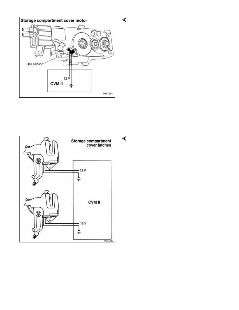
cover lock motor is on driveshaft tunnel
under rear seat. It consists of a motor
with Hall sensor, gear assembly and two
bowden cables connected to cover locks
on two sides of cover. The Hall sensor
detects locked/unlocked position of
cover.

During convertible top operation (raising
or lowering) CVM II signals General
Module (GM V) over K-bus to unlock
storage compartment. The lock motor
runs 180° to unlock cover latches. The
motor always turns in same direction to
lock or unlock.

Once motor has turned 180°, the Hall
sensor will signal GM V to switch off
motor. At the same time, GM V will
signal CVM II to continue top operation.

There are two storage compartment
cover lock Hall sensors, one mounted on
each storage cover latch. The switches
receive power and ground from CVM II.
Each switch input provides a high signal
when cover is unlocked and raised far
enough by cover hydraulic cylinders to
clear latches.

When cover is completely lowered by
hydraulic cylinders, the Hall sensors
send a signal to CVM II which signals
GM V to relock storage cover.


Top storage compartment floor

The trunk of the E46 Convertible offers
the variable convertible top storage
compartment floor. This feature allows
the luggage storage area to be enlarged
by approximately 40 liters (1.5 cu. ft.)

when soft top is raised or removed for
hard top installation.

The plastic variable compartment floor is
hinged at four point so that it can
articulate and be rotated up into top
storage space.

A lever on right side of variable floor
actuates and locks floor into position.

A dampening piston on right side
maintains position of variable floor. The
lower dampening piston hinge switches
a microswitch on right side of variable
floor when floor is in folded (raised)
position. This signal to CVM II locks out
operation of top.

541-2


Convertible Top
Components


Mechanical top components

The metal folding frame of the top is
bolted to the sides of the car behind
the door pillars (B-pillars).

The three layer soft top consists of:

Fabric outer layer

Middle fleece liner

Inner liner

Refer to the accompanying illustration
for mechanical component locations.


Convertible top
mechanical
components

1

-

Folding top

2

-

Folding top
frame

3

-

Base plate

4

-

Windshield
frame lock
microswitch

5

-

Windshield
frame lock drive
motor

6

-

Windshield

frame cover

7

-

Emergency
mechanism
cover

8

-

Emergency
operation crank

9

-

Tension rope
Insulation

10

-

Tension bow

11

-

Hall sensor

12

-

Gas pressurized
spring

13

-

Main pillar Hall
sensor

14

-

Console

15

-

Windshield
latch (left side)


Hydraulic system repairs

CAUTION!

When working on hydraulic
system, system must be at zero
pressure.

Disconnect supply and return
lines a with convertible top
stowed and in untensioned state.

Once hydraulic system has been
opened, a function test must be
carried out after work has been
completed.


Content   ..  231  232  233  234   ..