BMW 3 (E46). Manual - part 159
4
-
Upper control
arm outer bolt
self-locking M12
nut
tighten to 110 Nm
(81 ft-lb)
5
-
Trailing arm
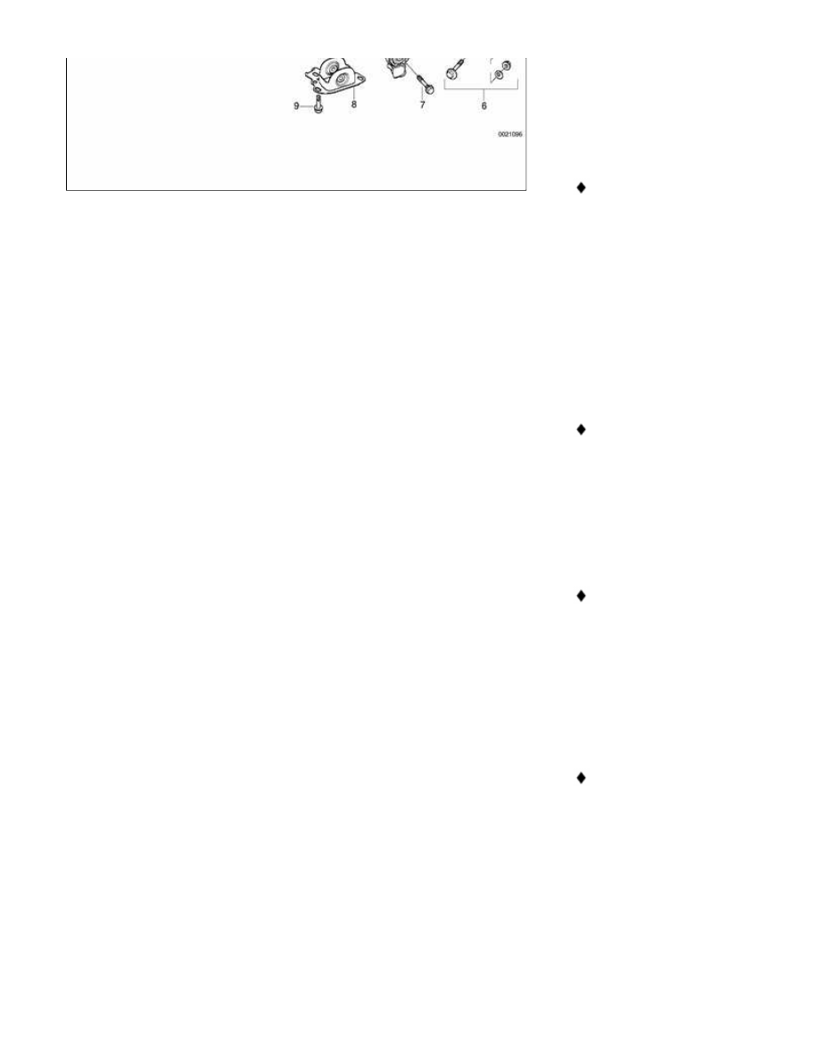
6
-
Lower control
arm eccentric
bolt eccentric
flat M12 washer
self locking M12
nut
tighten to 110 Nm
(81 ft-lb)
7
-
Trailing arm
front bolt
self-locking M12
nut
tighten to 110 Nm
(81 ft-lb)
8
-
Trailing arm
front bracket
9
-
Bracket
mounting bolt
tighten to 77 Nm (57
ft-lb)
10
-
Drive axle
11
-
Lower control
arm
12
-
Lower control
arm plastic
shield