BMW 3 (E46). Manual - part 157


  Index      BMW     BMW 3 (E46) - service repair manual 2006 year


Search            


Content   ..  155  156  157  158   ..


BMW 3 (E46). Manual - part 157


suspension.

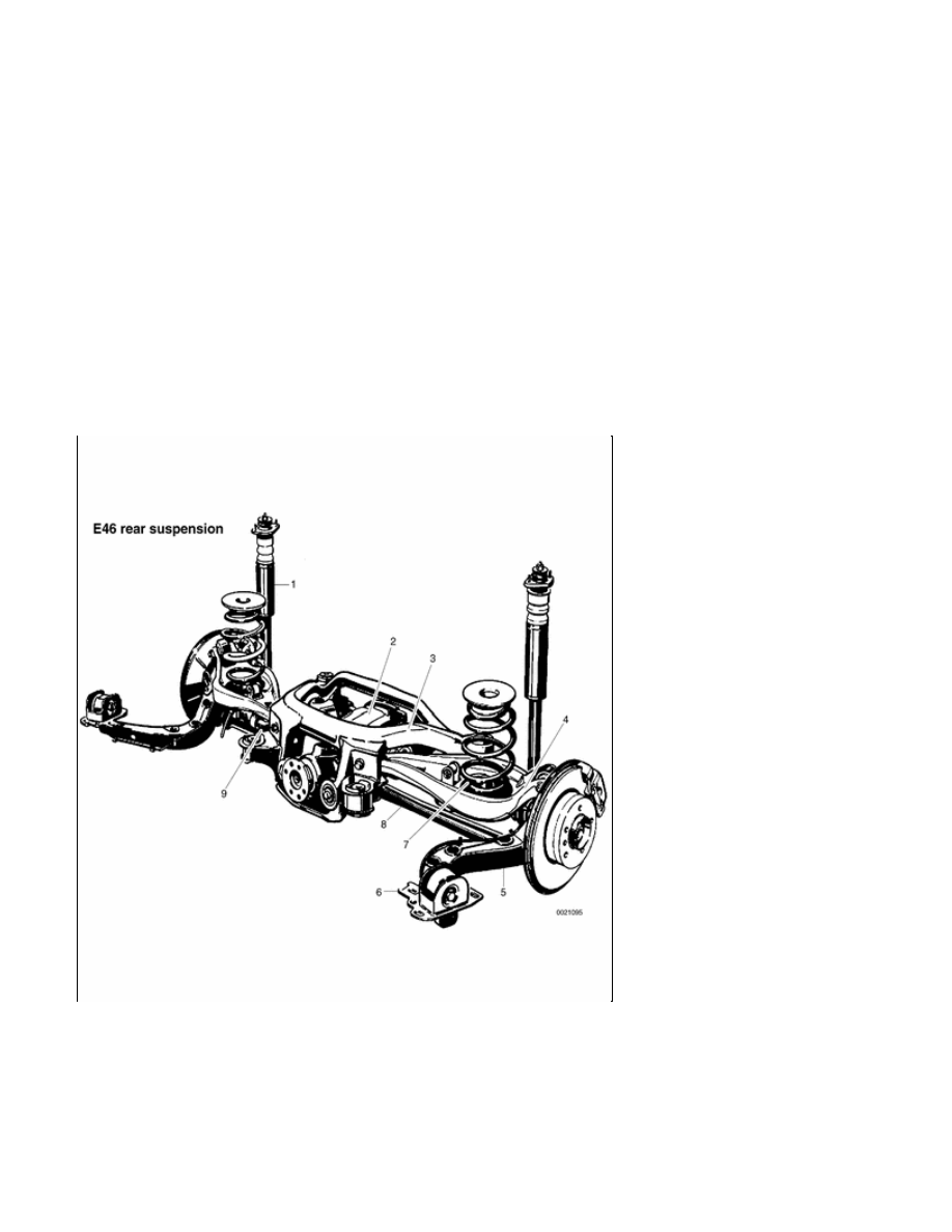
The rear subframe (final drive carrier)
supports the rear differential and
provides mounting points for the upper
and lower control arms. The upper
control arm on each side provide the
lower spring perch for the coil spring.
The upper and lower control arm on
each side are attached to the trailing
arm. The trailing arms contain the
wheel bearings for the rear drive hubs.
The rear brake calipers are bolted to
the trailing arms.


E46 Rear suspension

1

-

Shock absorber

2

-

Differential
housing

3

-

Rear subframe
(final drive
carrier)

4

-

Upper control
arm

5

-

Trailing arm

6

-

Trailing arm
bracket

7

-

Coil spring

8

-

Lower control
arm

9

-

Stabilizer bar


330-2


Rear Shock Absorbers
and Springs

Replace shock absorbers and springs
in pairs only.


Rear shock absorber, removing
and installing

 -

Raise car and remove rear wheels.

WARNING!

Make sure that the car is firmly
supported on jack stands designed
for the purpose. Place the jack
stands beneath a structural chassis
point. Do not place jack stands
under suspension parts.

Support trailing arm from below using
an adjustable jackstand. Remove
shock absorber lower mounting bolt
(arrow).

CAUTION!

The shock absorber prevents the
drive axle from dropping too far.
Support the trailing arm before
removing the lower shock absorber
bolt to avoid damage to drive axle CV
joints.

On Sedan or Coupe models: Working
in trunk, pry out luggage compartment
liner retaining clips. Peel back liner to
gain access to upper shock absorber
mounting nuts (arrows).

 -

On Convertible models: Open
convertible top storage

compartment to access upper
shock absorber mount.

 -

On Sport Wagon models: Working
in cargo compartment, remove
side trim next to rear seat
backrests.

 -

Support shock absorber from
below while removing upper
mounting nuts. Lower shock
absorber out of wheel housing.

Transfer shock top mounting plate,
dust cover (if applicable) and related
components to new shock absorber.

1 - Self-locking nut M10 -tighten to 14

Nm (10 ft-lb)

2 - Upper support plate

3 - Top mount

4 - Body seal

5 - Lower support plate

6 - Spacer ring

7 - Rubber bump stop

8 - Self-locking nut M8 -tighten to 24

Nm (17 ft-lb)

 -

Installation on car is reverse of
removal, noting the following:

Make sure all threaded bolts, nuts
and mating surfaces are clean.

Install shock absorber into shock
tower using a new upper
mounting seal and new
self-locking nuts.

Make sure rectangular thrust
washer on lower mounting bolt is
between bolt head and shock
absorber rubber.

Tighten lower shock absorber bolt
to its final torque once car is on
ground.

Tightening torques

Road wheel to hub

100 ± 10 Nm

(74 ± 7 ft-lb)

Shock absorber to
trailing arm (car in
normal loaded
position)

100 Nm (74

ft-lb)

Shock absorber to
upper mount

14 Nm (10 ft-lb)

Shock absorber
upper mount to
body M8
self-locking nuts

28 Nm (21 ft-lb)


Coil spring, removing and
installing

 -

Raise car and remove rear wheel.

Remove drive axle to final drive
mounting bolts (arrows).

Detach drive axle from final drive.

Suspend drive axle from chassis
using stiff wire.

 -

Remove fuel tank protective panel.

 -

Detach stabilizer bar from rear


Content   ..  155  156  157  158   ..