Acura CSX. Manual - part 610


  Index      Acura     Acura CSX - P/NO. 61SNR03 - service repair manual 2006-2009 year


Search            


Content   ..  608  609  610  611   ..


Acura CSX. Manual - part 610


01

02

03

SNR9ANDJ36100042525KDAT00

23-154

Navigation System

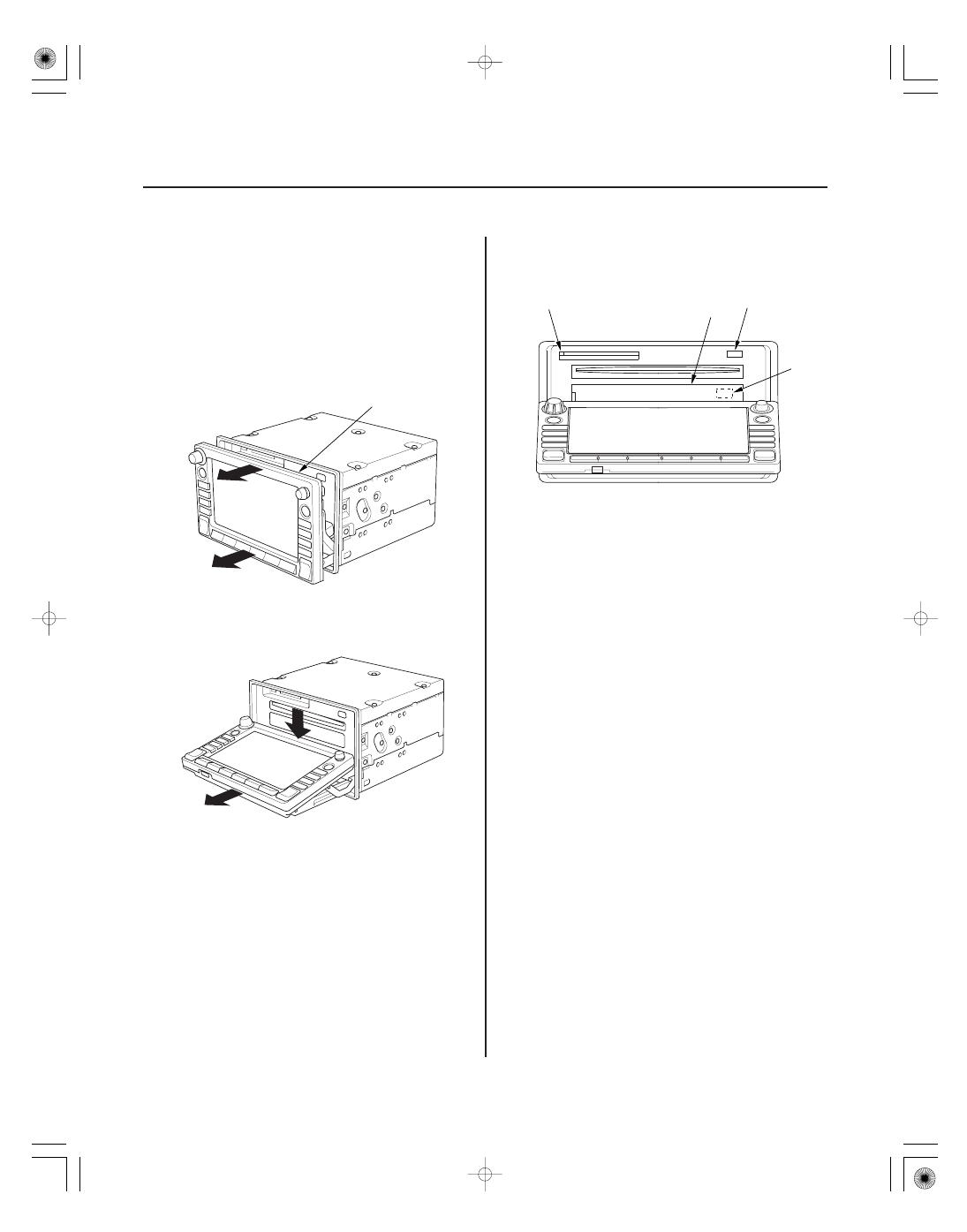
CD, DVD, and PC Card Removal/Installation

A

A

D

B

C

If the displays Open/Close button does not work, you
must manually open the display to obtain the client’s
Navigation DVD, CD and possibly their PC card. Follow
the step below:

1. Remove the navigation unit from the vehicle

(see page 23-155).

2. On the bench, carefully pull the display (A) straight

out (about 1/2 inch).

3. Fold down the display as shown in the diagram

below.

4. Push the PC card eject button (A) to eject the client’s

PC card (if installed). Power is not required for this
function.

5. Remove the plastic cover (B) the navigation DVD

slot.

6. With the display open, temporarily reconnect the

unit in the dash (to power it up).

7. Push the CD eject button (C), and navigation DVD

eject button (D) (the button is behind the plastic
cover and works only when the unit is powered)
and remove the discs (holding the discs by their
edges to avoid fingerprints). To avoid scratches,
place the navigation DVD, and client’s CD in a jewel
case if available.

8. Re-attach the plastic cover that hides the navigation

DVD slot.

9. Close the display by first returning the display to

the upward position, and then pushing the entire
display straight back into the unit.

10. After installing the new navigation unit, re-insert

the navigation DVD, the client’s CD, and PC card.

08/08/21 14:08:38 61SNR030_230_0157

01

SNR9ANDJ36100042521KDAT01

23-155

Navigation Unit Removal/Installation

A

B

B

C

SRS components are located in this area. Review the
SRS component location (see page 24-11).
Also review the precautions and procedures (see page
24-13) in the SRS section before doing repairs or
service.

NOTE:

• Put on gloves to protect your hands.
• Take care not to scratch the dashboard and related

parts.

• Lay a workshop towel under the parts when working

on them to protect the face panel from scratches or
other damage.

• Do not work in a dusty or dirty place.
• Discharge static electricity from your body before and

during the work.

• Do not touch the circuit board(s) with your bare

hands.

• Do not work with dirty hands.
• Be careful not to fold the flat plate cable.
• Do not touch the terminal connector of the flat plate

cable with your bare hands. (If you have touched it,
wipe it off thoroughly.)

• Before replacing the navigation unit, make sure to

remove the client’s navigation DVD, and their audio
CD, or PC card. Remanufactured navigation units do
not come with a navigation DVD. Re-install the client’s
navigation DVD, audio CD, and audio PC card into the
new Remanufactured unit. If the navigation display
won’t open, manually remove the navigation DVD,
audio CD, and PC card (see page 23-154).

• If you are replacing the navigation unit, write down

the audio presets (if possible), then enter then into
the new navigation unit.

1. Make sure you have the 4-digit anti-theft code for

the navigation system.

2. Eject the DVD from the original navigation unit. To

avoid scratching or damaging the DVD, temporarily
place the DVD in a jewel case.

3. Remove the meter inner visor (see page 20-100).

4. Remove the center pocket hole lid and bolts, then

pull out the center panel (A).

5. Disconnect the connectors (B) and the air hose (C),

then remove the center panel.

08/08/21 14:08:39 61SNR030_230_0158

01

01

SNR9ANDJ36100063301FEAT00

Position

Resistance

23-156

23-156

Navigation System

Voice Control Switch Test

A

B

C

6. Remove the screws, brackets (A), and the

navigation unit (B) from the center panel (C).

7. Install the navigation unit in the reverse order of

removal, and make sure all connectors are secure.

8. Turn the ignition switch to ON (II), then reinstall the

client’s original DVD, verifying that the DVD is free
of scratches or smudges.

9. Check any official Honda service website for more

service information about the navigation system.

NOTE: Simply transferring the DVD from the
original navigation unit to the new navigation unit
does not assure the correct software for the vehicle
will be loaded into the new navigation unit. Doing
the DVD transfer without doing software patches
may cause the new navigation unit to appear to be
malfunctioning.

10. Enter the new navigation anti-theft code.

11. Park the vehicle outside, and do the GPS

initialization (see page 23-93).

12. Give the new navigation anti-theft code to the client.

1. Remove the voice control switch (see page 23-157).

2. Measure the resistance between terminals No. 2

and No. 4 in each switch position according to the
table.

No button pressed

About 10 k

TALK

About 2.9 k

BACK

About 680

3. If the resistance is not as specified, replace the

voice control switch (see page 23-157).

08/08/21 14:08:39 61SNR030_230_0159

01

01

SNR9ANDJ36100063301FEAT00

Position

Resistance

23-156

23-156

Navigation System

Voice Control Switch Test

A

B

C

6. Remove the screws, brackets (A), and the

navigation unit (B) from the center panel (C).

7. Install the navigation unit in the reverse order of

removal, and make sure all connectors are secure.

8. Turn the ignition switch to ON (II), then reinstall the

client’s original DVD, verifying that the DVD is free
of scratches or smudges.

9. Check any official Honda service website for more

service information about the navigation system.

NOTE: Simply transferring the DVD from the
original navigation unit to the new navigation unit
does not assure the correct software for the vehicle
will be loaded into the new navigation unit. Doing
the DVD transfer without doing software patches
may cause the new navigation unit to appear to be
malfunctioning.

10. Enter the new navigation anti-theft code.

11. Park the vehicle outside, and do the GPS

initialization (see page 23-93).

12. Give the new navigation anti-theft code to the client.

1. Remove the voice control switch (see page 23-157).

2. Measure the resistance between terminals No. 2

and No. 4 in each switch position according to the
table.

No button pressed

About 10 k

TALK

About 2.9 k

BACK

About 680

3. If the resistance is not as specified, replace the

voice control switch (see page 23-157).

08/08/21 14:08:39 61SNR030_230_0159


Content   ..  608  609  610  611   ..