Acura CSX. Manual - part 597
*02
*03
−
−
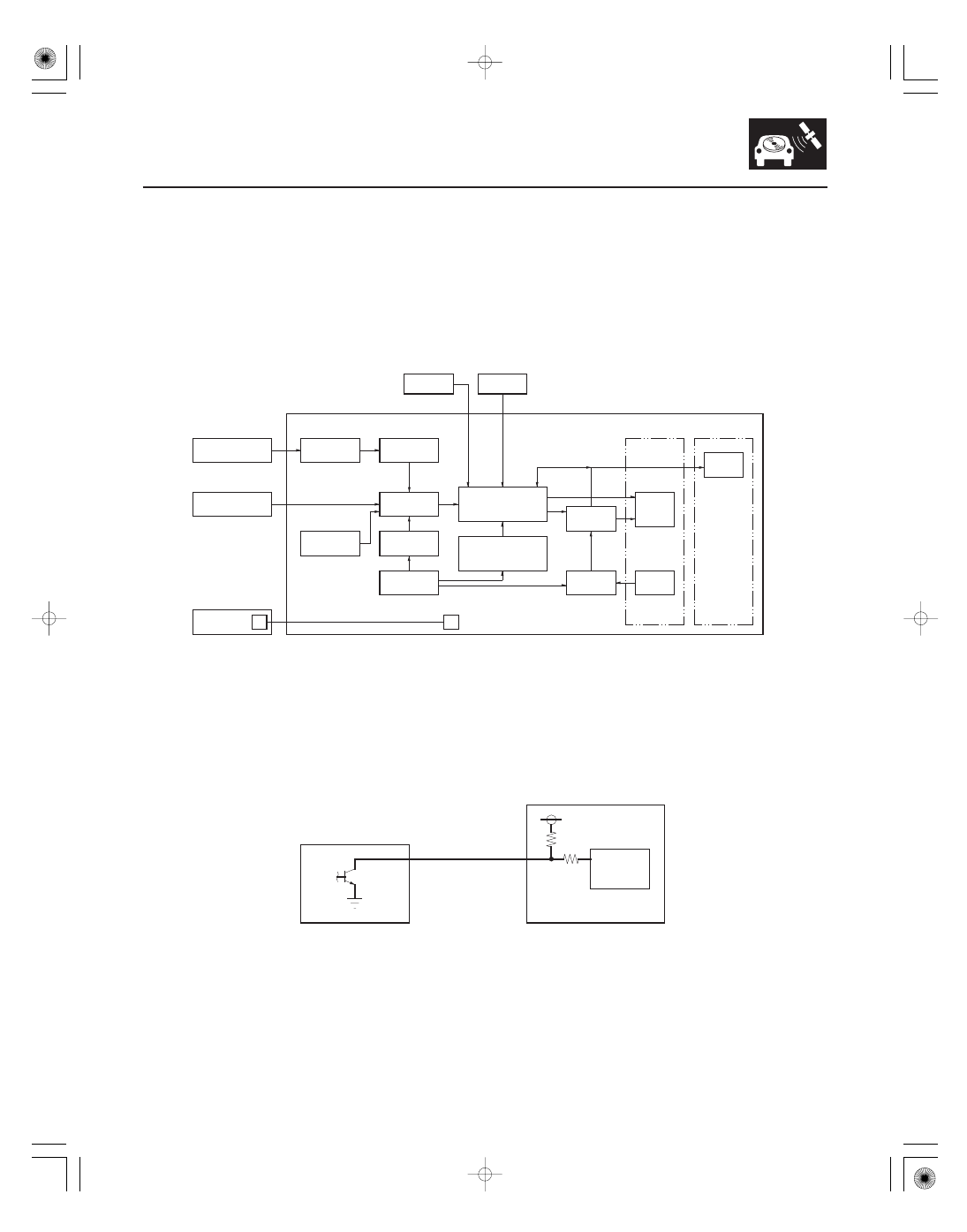
Navigation Function
Function Diagram
Vehicle Speed Pulse
23-103
STEERING BUTTONS
MICROPHONE
GA Net bus
AUDIO UNIT
LCD
SWITCH
Destination
DVD ROM
YAW RATE SENSOR
GPS tuning
GPS RECEIVER
NAVIGATION UNIT
XM RECEIVER
GPS ANTENNA
Reception of radio
wave from satellite
Data pcocess
concerning map
and vehivle position
Perception of
vehicle position
ECM/PCM
(VEHICLE SPEED PULSE)
Detection of
travel distansce
Detection of
vehicle position
Detection of
direction change
Correction of
map matching
Map scroll
Change of reduced
scale of map
Guide
processing
Audio
guidance
NAVIGATION
DISPLAY
VOICE
PROMPTS
Sensor power
NAVIGATION UNIT
ECM/PCM
DISTANCE
DETECTION
CIRCUIT
The navigation system is composed of the navigation unit, the ECM/PCM (vehicle speed signal), the GPS antenna, the
microphone, the voice control switch, the XM receiver, and the climate control unit.
These units communicate with each other on the GA-Net bus.
The vehicle speed pulse is sent by the ECM/PCM. The ECM/PCM receives a signal from the countershaft speed sensor,
then it processes the signal, and transmits it to the speedometer and other systems.
08/08/21 14:06:27 61SNR030_230_0106