Acura CSX. Manual - part 503
+
+
―――
―――
+
―――
―――
―――
02
Fuse
Number
Amps
Component(s) or Circuit(s) Protected
22-63
2 3 4 5
1
1617
19
18
20
11
12
14
13
15
2627
29
28
30
2122
24
23
25
36 37
38
3132
34
33
35
10
6 7 8 9
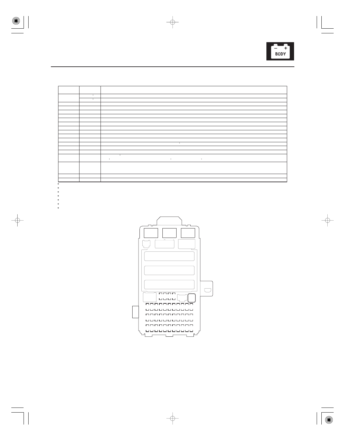
21
20 A
MICU (
B H/L LO)
30 A
MICU (
B H/L LO)
22
Not used
23
Not used
24
20 A
Moonroof control unit/motor
25
20 A
MICU (
B DR LOCK)
26
20 A
Driver’s power window motor (via power window master switch)
27
Not used
28
15 A
Console accessory power socket (via console accessory power socket relay)
29
15 A
Front accessory power socket (via front accessory power socket relay)
30
20 A
Front passenger’s power window motor
31
Not used
32
20 A
Moonroof control unit/motor, Moonroof switch , Right rear power window motor
33
20 A
Left rear power window motor
34
Not used
35
7.5 A
Audio unit , Console accessory power socket relay, Front accessory power socket relay, HandsFreeLink control
unit , Ignition key switch, Navigation unit , Stereo amplifier
36
10 A
Climate control unit, Driver’s seat heater switch, Fan control relay and radiator fan relay (via A/C diode),
Passenger’s seat heater switch, Power mirrors (via power mirror switch), Under-hood fuse/relay box (A/C
compressor clutch relay, Blower motor relay, Power mirror defogger relay, Rear window defogger relay)
37
7.5 A
MICU (daytime running lights power supply)
38
30 A
MICU (IG 1 WIPER)
1: ’06-07 models
2: TYPE S model
3: Without HID
4: With HID
5: ’09 model with navigation system
6: Without navigation system
7: With navigation system
3
4
1
6
5
7
2
08/08/21 14:24:03 61SNR030_220_0065