Acura CSX. Manual - part 447


  Index      Acura     Acura CSX - P/NO. 61SNR03 - service repair manual 2006-2009 year


Search            


Content   ..  445  446  447  448   ..


Acura CSX. Manual - part 447


06

SNR9A00J26220219251KDAT00

SNR9A00J26220200000KDAT00

Special Tools Required

Special Tools Required

20-108

20-108

Dashboard

Side Defogger Vent Trim Removal/
Installation

Dashboard/Steering Hanger Beam
Removal/Installation
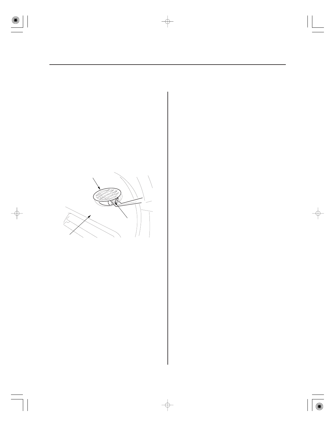
A

B

C

KTC trim tool set SOJATP2014

NOTE:

• Use the appropriate tool from the KTC trim tool set to

avoid damage when removing components.

• Take care not to scratch the dashboard and related

parts.

1. Insert the trim tool into a gap between the side

defogger vent trim (A) and the dashboard (B), and
release the hook (C).

2. Install the side defogger vent trim in the reverse

order of removal.

KTC trim tool set SOJATP2014

SRS components are located in this area. Review the
SRS component locations (see page 24-11) and the
precautions and procedures (see page 24-13) before
doing repairs or service.

NOTE:

• Use the appropriate tool from the KTC trim tool set to

avoid damage when removing components.

• Have an assistant help you when removing and

installing the dashboard/steering hanger beam.

• Take care not to scratch the dashboard, the body and

other related parts.

• Put on gloves to protect your hands.

1. Do the battery terminal disconnection procedure

(see page 22-68), and wait at least 3 minutes before
beginning work.

2. Remove these items:

• Driver’s dashboard lower cover (see page

20-102)

• Driver’s dashboard undercover (see page 20-103)
• Passenger’s dashboard undercover (see page

20-104)

• Center console (see page 20-92)
• Glove box (see page 20-104)
• Kick panel, both sides (see page 20-66)
• A-pillar trim, both sides (see page 20-69)
• Steering column (see page 17-10)
• EPS control unit (see page 17-84)

08/08/21 15:02:57 61SNR030_200_0110

07AAC-SEPA240

07AAC-SEPA240

01

01

03

Driver’s side

Middle portion

20-109

Fastener Location

6 x 1.0 mm
9.8 N·m
(1.0 kgf·m,
7.2 lbf·ft)

A

C

B

D

E

: Bolt, 1

C

E

C

C

A

B

D
6 x 1.0 mm
9.8 N·m
(1.0 kgf·m, 7.2 lbf·ft)

C

C

A

3. Remove the bolt securing the under-dash fuse/

relay box (A). Disconnect the roof wire harness
connector (B), then lower the box.

4. From under the dash, disconnect the engine

compartment wire harness connectors (C), driver’s
door wire harness connectors (D), and the floor
wire harness connectors (E) from the dashboard
wire harness connectors or the under-dash fuse/
relay box.

5. Disconnect the SRS unit connector A, the antenna

connector (B), and detach the wire harness clips (C).
Remove the ground bolt (D) with a TORX T30 bit.

6. Disconnect the A/C subharness connector (A) in the

glove box opening.

Use a TORX T30 bit.

08/08/21 15:02:57 61SNR030_200_0111

04

05

Passenger’s side

20-110

Dashboard

A

A

B

C

D

E

A

C

A

C

D

D

8 x 1.25 mm

7. From under the dash, disconnect the passenger’s

door wire harness connectors (A).

8. Remove the special bolts (A) from outside the

passenger’s door.

–1 Remove the caps (B).
–2 Loosen the special bolts until they disengage

from the threads on the hanger beam sleeves
(C). Continue loosening the bolts until they
engage the inside threads of the adjusting nuts
(D). The thread lock on the special bolts makes
the special bolts and the adjusting nuts turn
together.

–3 Tighten the special bolts to turn the adjusting

nuts until they bottom in the sleeves. This
creates a gap (E) between the adjusting nuts
and the body.

–4 Loosen the special bolts to disengage them

from the adjusting nuts. Remove the special
bolts.

08/08/21 15:02:58 61SNR030_200_0112

05

07

02

20-111

A

B

C

B

C

A

21 mm (0.83 in.)

6 x 1.0 mm
9.8 N·m
(1.0 kgf·m,
7.2 lbf·ft)

A

B

D

D

8 x 1.25 mm
22 N·m
(2.2 kgf·m, 16 lbf·ft)

B

B

D

D

6 x 1.0 mm
9.8 N·m
(1.0 kgf·m,
7.2 lbf·ft)

C
8 x 1.25 mm
22 N·m
(2.2 kgf·m, 16 lbf·ft)

Fastener Locations

: Bolt, 3

: Bolt, 1

: Bolt, 4

B

C

D

9. If necessary, remove the dashboard side cover (A).

–1 Gently pull out along the rear edge to release

the hooks (B).

–2 Gently pull out on the side cover to release the

hooks (C), then remove the side cover.

10. If the adjusting nuts (A) are not screwed fully into

the sleeve after removing the special bolts, screw
the externally threaded nuts into the sleeves with a
21 mm open-end wrench. In this case, the special
bolts should be replaced with new ones because
the thread lock is worn out.

11. Remove the caps (A), then remove the bolts

(B, C, D) from outside the driver’s door.

08/08/21 15:02:59 61SNR030_200_0113


Content   ..  445  446  447  448   ..