Acura CSX. Manual - part 407


  Index      Acura     Acura CSX - P/NO. 61SNR03 - service repair manual 2006-2009 year


Search            


Content   ..  405  406  407  408   ..


Acura CSX. Manual - part 407


02

03

04

Sign

YES

NO

YES

NO

YES

NO

VSA Modulator-
control Unit 37P

Connector Terminal

Steering Angle

Sensor 5P

Connector Terminal

19-133

VSA MODULATOR-CONTROL UNIT 37P CONNECTOR

STEERING ANGLE SENSOR 5P CONNECTOR

STR-B
(PUR)

SVCC
(ORN) SGND (BRN)

SVCC (ORN)

SGND (BRN)

STR-B
(PUR)

STR-A (GRN)

STR-A (GRN)

STEERING ANGLE SENSOR 5P CONNECTOR

STR-A (GRN)

STR-B (PUR)

STEERING ANGLE SENSOR 5P CONNECTOR

STR-A
(GRN)

STR-B (PUR)

SVCC
(ORN)

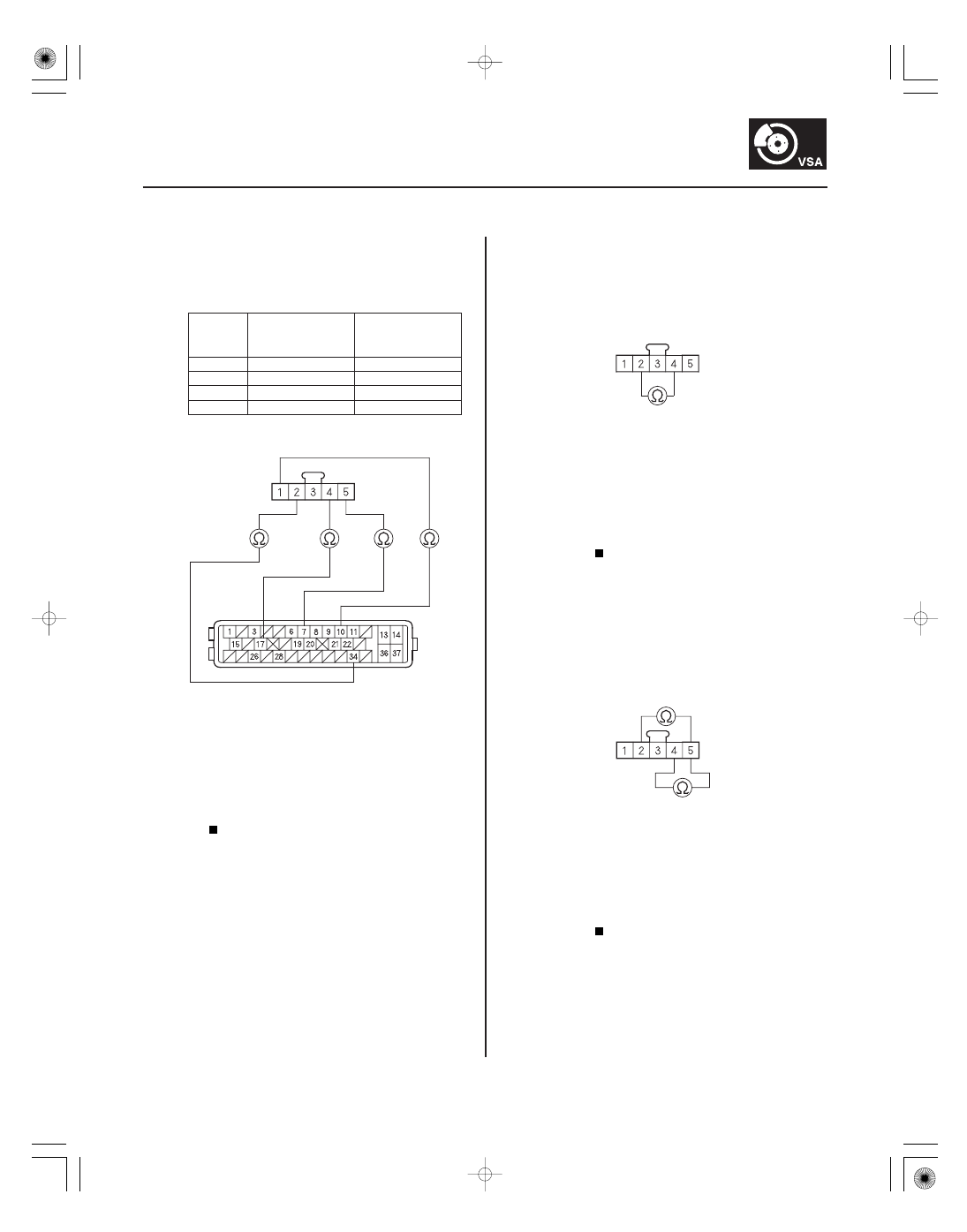
7. Check for continuity between the VSA modulator-

control unit 37P connector terminal and the
steering angle sensor 5P connector terminal
individually.

STR-A

No. 34

No. 2

STR-B

No. 17

No. 4

SVCC

No. 7

No. 5

SGND

No. 10

No. 1

Go to step 8.

Repair open in the wire between the steering

angle sensor and the VSA modulator-control
unit.

8. Check for continuity between steering angle sensor

5P connector terminals No. 2 and No. 4.

Repair short in the wires between the

steering angle sensor and the VSA modulator-
control unit.

Go to step 9.

9. Check for continuity between steering angle sensor

5P connector terminals No. 5 and No. 2, and
between No. 5 and No. 4 individually.

Repair short in the wires between the

steering angle sensor and the VSA modulator-
control unit.

Go to step 10.

Wire side of female terminals

Wire side of female terminals

Wire side of female terminals

Wire side of female terminals

Is ther e continuity?

Is ther e continuity?

Is ther e continuity?

08/08/21 15:05:55 61SNR030_190_0133

05

06

YES

NO

YES

NO

19-134

VSA System Components

STEERING ANGLE SENSOR 5P CONNECTOR

STR-A (GRN)

STR-B (PUR)

SGND
(BRN)

STEERING ANGLE SENSOR 5P CONNECTOR

STR-A (GRN)

STR-B (PUR)

10. Check for continuity between steering angle sensor

5P connector terminals No. 1 and No. 2, and
between No. 1 and No. 4 individually.

Repair short in the wires between the

steering angle sensor and the VSA modulator-
control unit.

Go to step 11.

11. Turn the ignition switch to ON (II).

12. Measure the voltage between body ground and

steering angle sensor 5P connector terminals No. 2
and No. 4 individually.

Repair short to power in the wire between

the steering angle sensor and the VSA modulator-
control unit.

Replace the steering angle sensor (see page

19-168).

Wire side of female terminals

Wire side of female terminals

Is ther e continuity?

Is ther e 0.1 V or mor e?

08/08/21 15:05:55 61SNR030_190_0134

SNR9AC7K801000R2723FAAT00

SNR9AC7K801000R2724FAAT00

DTC 27-23:

DTC 27-24:

YES

NO

YES

NO

19-135

19-135

Steering Angle Sensor Counter

Malfunction

Steering Angle Sensor Exchange

Malfunction

1. Turn the ignition switch to ON (II).

2. Clear the DTC with the HDS.

3. Turn the ignition switch to LOCK (0), then turn it to

ON (II) again.

4. Turn the steering wheel from lock to lock.

5. Check for DTCs with the HDS.

Replace the steering angle sensor (see page

19-168).

Intermittent failure, the system is OK at this

time.

1. Turn the ignition switch to ON (II), and set the front

wheels to the straight ahead position.

2. Turn the steering wheel one turn to the left. Check

the STEERING ANGLE in the VSA DATA LIST with
the HDS.

Intermittent failure, the system is OK at this

time.

Replace the steering angle sensor (see page

19-168).

Is DT C 27 -23 indicated?

Is ther e about 288 degr ees to 432 degr ees
positive?

08/08/21 15:05:55 61SNR030_190_0135

SNR9AC7K801000R31XXFAAT00

DTC 31-xx :

DTC 32-xx :

DTC 33-xx :

DTC 34-xx :

DTC 35-xx :

DTC 36-xx :

DTC 37-xx :

DTC 38-xx :

Subcode

Malfunction

Note (DTC)

YES

NO

19-136

VSA System Components

ABS Right-front Inlet Solenoid

Valve Malfunction

ABS Right-front Outlet Solenoid

Valve Malfunction

ABS Left-front Inlet Solenoid

Valve Malfunction

ABS Left-front Outlet Solenoid

Valve Malfunction

ABS Right-rear Inlet Solenoid

Valve Malfunction

ABS Right-rear Outlet Solenoid

Valve Malfunction

ABS Left-rear Inlet Solenoid

Valve Malfunction

ABS Left-rear Outlet Solenoid

Valve Malfunction

: Any two-character subcode (see table)

01

Solenoid Initial
Pulse

31-01, 32-01, 33-01,
34-01, 35-01, 36-01,
37-01, 38-01

21

Solenoid Pulse

31-21, 32-21, 33-21,
34-21, 35-21, 36-21,
37-21, 38-21

22

Solenoid
Speculative

31-22, 32-22, 33-22,
34-22, 35-22, 36-22,
37-22, 38-22

23

Solenoid Stuck
ON

31-23, 32-23, 33-23,
34-23, 35-23, 36-23,
37-23, 38-23

1. Turn the ignition switch to ON (II).

2. Clear the DTC with the HDS.

3. Turn the ignition switch to LOCK (0), then turn it to

ON (II) again.

4. Check for DTCs with the HDS.

Replace the VSA modulator-control unit

(see page 19-171).

Intermittent failure, the system is OK at this

time.

Is DT C 31-xx, 32-xx, 33-xx, 34-xx, 35-xx, 36-xx,
37 -xx, or 38-xx indicated?

08/08/21 15:05:56 61SNR030_190_0136


Content   ..  405  406  407  408   ..