Acura CSX. Manual - part 392
SNR9AC6K701000R1223FAAT00
SNR9AC6K701000R2111FAAT00
−
−
−
−
−
−
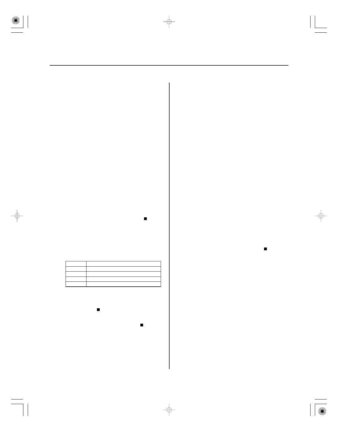
DTC 12-23:
DTC 14-23:
DTC 16-23:
DTC 18-23:
DTC 21-11:
DTC 22-11:
DTC 23-11:
DTC 24-11:
YES
NO
DTC
Appropriate Wheel Speed Sensor
YES
NO
YES
NO
19-72
19-72
ABS Components
Right-front Wheel Speed Sensor
Installation Error (0 to 15 km/h (0 to 9 mph))
Left-front Wheel Speed Sensor
Installation Error (0 to 15 km/h (0 to 9 mph))
Right-rear Wheel Speed Sensor
Installation Error (0 to 15 km/h (0 to 9 mph))
Left-rear Wheel Speed Sensor
Installation Error (0 to 15 km/h (0 to 9 mph))
Right-front Magnetic Encoder
(Wheel Bearing) Malfunction (Pulse Missing)
Left-front Magnetic Encoder
(Wheel Bearing) Malfunction (Pulse Missing)
Right-rear Magnetic Encoder
(Wheel Bearing) Malfunction (Pulse Missing)
Left-rear Magnetic Encoder
(Wheel Bearing) Malfunction (Pulse Missing)
1. Test-drive the vehicle between 1 km/h (1 mph) and
15 km/h (9 mph).
NOTE: Drive the vehicle on the road, not on a lift.
2. Check the RF, LF, RR, LR WHEEL SPEED in the ABS
DATA LIST with the HDS.
Intermittent failure, the system is OK at this
time. Check for loose terminals between the wheel
speed sensor 2P connector and the ABS modulator-
control unit 25P connector. Refer to intermittent
failures troubleshooting (see page 19-50).
Go to step 3.
3. Turn the ignition switch to LOCK (0).
4. Check that the appropriate wheel speed sensor is
properly mounted (see page 19-92).
12-23
Right-front
14-23
Left-front
16-23
Right-rear
18-23
Left-rear
Replace the appropriate wheel speed sensor
(see page 19-92).
Reinstall the wheel speed sensor, and check
the mounting position (see page 19-92).
1. Turn the ignition switch to ON (II).
2. Clear the DTC with the HDS.
3. Test-drive the vehicle at 20 km/h (13 mph) or more,
and go a distance of 100 m (328 ft) or more.
NOTE: Drive the vehicle on the road, not on a lift.
4. Check for DTCs with the HDS.
Go to step 5.
Intermittent failure, the system is OK at this
time. Check for loose terminals between the wheel
speed sensor 2P connector and the ABS modulator-
control unit 25P connector. Refer to intermittent
failures troubleshooting (see page 19-50).
5. Turn the ignition switch to LOCK (0).
Ar e all f our values the same?
Is the wheel speed sensor installation OK ?
Is DT C 21-11, 22-11, 23-11, and/ or 24-11
indicated?
08/08/21 15:03:14 61SNR030_190_0072