Acura CSX. Manual - part 356


  Index      Acura     Acura CSX - P/NO. 61SNR03 - service repair manual 2006-2009 year


Search            


Content   ..  354  355  356  357   ..


Acura CSX. Manual - part 356


*01

*02

SNR9A00B20200014202KBAT00

Special Tools Required

18-13

Ball Joint Boot Inspection/Replacement
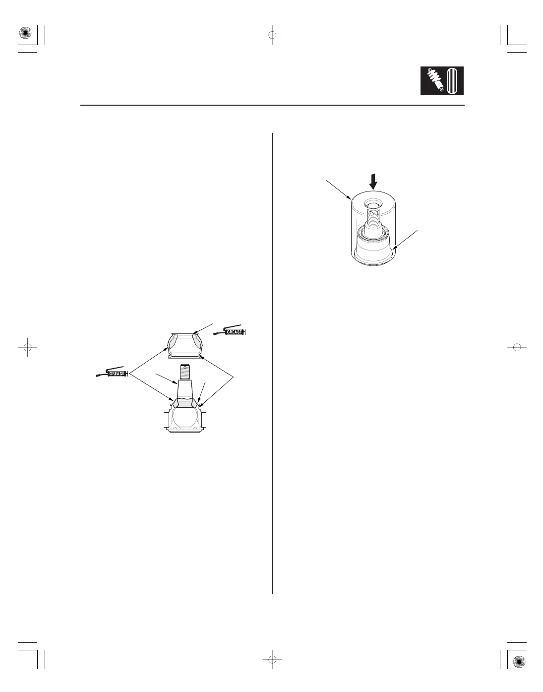
A

B

C

D

(Multipurpose)

(Multipurpose)

A

07GAF-SE00200

Press

Attachment, 40 mm 07GAF-SE00200

1. Check the ball joint boot for weakness, damage,

cracks, and grease leaks.

NOTE:

• If the ball joint boot is damaged with grease leaks,

replace the appropriate part as an assembly.

• If the ball joint boot is soft and cracked without

grease leaks, go to step 2. Replace the
appropriate ball joint boot.

2. Disconnect the appropriate ball joint connection,

and remove the component including the ball joint.
The lower ball joint (see page 18-20).

3. Remove the boot.

4. Pack the interior and lip (A) of a new boot with

grease. Keep the grease off of the boot-to-lower
ball joint housing mating surfaces (B).

5. Pack fresh grease into the base (C). Do not let dirt

or other foreign materials get into the boot.

6. Install the boot on the ball joint, then squeeze it

gently to force out any air, then wipe the grease off
the tapered portion of the ball joint pin (D).

7. Press the boot with the attachment until the bottom

seats on the lower ball joint housing (A) all the way
around.

8. After installing a boot, wipe any grease off the

exposed portion of the ball joint pin.

9. Install all of the removed parts.

08/08/21 14:56:49 61SNR030_180_0013

*01

SNR9A00B20200036401KBAT00

Exploded View

18-14

Front Suspension

Knuckle/Hub/Wheel Bearing Replacement

SNAP RING

SELF-LOCKING NUT

DAMPER PINCH BOLT
14 x 1.5 mm
90 N·m
(9.2 kgf·m, 67 lbf·ft)

WHEEL BEARING
(MAGNETIC ENCODER)

SPLASH GUARD

KNUCKLE

FLAT SCREW
6 x 1.0 mm
9.8 N·m
(1.0 kgf·m, 7.2 lbf·ft)

FRONT HUB

FRONT BRAKE DISC

SPINDLE NUT
Except Type S model:
22 x 1.5 mm
181 N·m (18.5 kgf·m, 134 lbf·ft)

5 x 0.8 mm
6 N·m
(0.6 kgf·m, 4 lbf·ft)

Type S model:
24 x 1.5 mm
245 N·m (25.0 kgf·m, 181 lbf·ft)

Replace.

Replace.

Replace.

Check for corrosion,
deformation, and damage.
Replace if rusted.

Check for deformation and damage.

Apply a small amount of engine oil
to the seating surface of the nut.

Check for damage and cracks.

Check for wear, damage, and rust.

Replace.

Replace.

08/08/21 14:56:49 61SNR030_180_0014

02

02

04

Special Tools Required

Knuckle/Hub Replacement

18-15

A
108 N·m
(11.0 kgf·m,
79.6 lbf·ft)

B
12 x 1.25 mm
108 N·m (11.0 kgf·m, 79.6 lbf·ft)

A
8 x 1.25 mm
22 N·m
(2.2 kgf·m,
16 lbf·ft)

C

6 x 1.0 mm
9.8 N·m (1.0 kgf·m, 7.2 lbf·ft)

A

B

• Ball joint thread protector, 12 mm 07AAF-SDAA100
• Ball joint remover, 28 mm 07MAC-SL0A202
• Ball joint thread protector, 14 mm 071AF-S3VA000
• Ball joint remover, 32 mm 07MAC-SL0A102
• Hub dis/assembly tool, 40 mm 07GAF-SE00100
• Hub dis/assembly tool, 42 mm 07GAF-SD40100
• Driver handle 07749-0010000
• Attachment, 62 x 68 mm 07746-0010500
• Attachment, 70 x 90 mm

07GAD-SD40101

• Support base 07965-SD90100

1. Raise the front of the vehicle, and support it with

safety stands in the proper locations (see page
1-11).

2. Remove the wheel nuts (A) and front wheel.

3. Remove the brake hose mounting bolt (A) from the

damper.

4. Remove the brake caliper bracket mounting bolts

(B), then remove the caliper assembly (C) from the
knuckle. To prevent damage to the caliper
assembly or the brake hose, use a short piece of
wire to hang the caliper assembly from the
undercarriage. Do not twist the brake hose
excessively.

5. Remove the wheel speed sensor (A) from the

knuckle (B). Do not disconnect the wheel speed
sensor connector.

08/08/21 14:56:50 61SNR030_180_0015

03

*03

04

18-16

Front Suspension

A

B
Except Type S model:
22 x 1.5 mm
181 N·m
(18.5 kgf·m, 134 lbf·ft)

Type S model:
24 x 1.5 mm
245 N·m
(25.0 kgf·m, 181 lbf·ft)

B
12 x 1.25 mm
54 N·m
(5.5 kgf·m,
40 lbf·ft)

A

07MAC-SL0A202

07AAF-SDAA100

D
12 x 1.25 mm
59 N·m
(6.0 kgf·m,
43 lbf·ft)

B
12 x 1.25 mm
59 N·m
(6.0 kgf·m, 43 lbf·ft)

C
12 x 1.25 mm
59 N·m (6.0 kgf·m, 43 lbf·ft)

A

E

6. Raise the stake (A), then remove the spindle nut (B).

7. Remove the front brake disc (see page 19-21).

8. Check the front hub for damage and cracks.

9. Remove the cotter pin (A) from the tie-rod end ball

joint, then remove the nut (B).

NOTE: During installation, install a new cotter pin
after tightening the nut, and bend its end as shown.

10. Disconnect the tie-rod end ball joint from the

knuckle using the ball joint thread protector and the
ball joint remover (see page 18-12).

11. Remove the flange bolt and the self-locking nuts

from the lower arm (A).

NOTE: During installation, install the new flange
bolt and the new self-locking nuts. After lightly
tightening all three fasteners, tighten them to the
specified torque in the following order; the nut on
the front (B), the nut on the rear (C), then the bolt
(D).

12. Disconnect the lower ball joint (E) from the lower

arm.

Replace.

Replace.

Replace.

Replace.

Replace.

Replace.

08/08/21 14:56:50 61SNR030_180_0016


Content   ..  354  355  356  357   ..