Acura CSX. Manual - part 325
02
04
05
06
16-5
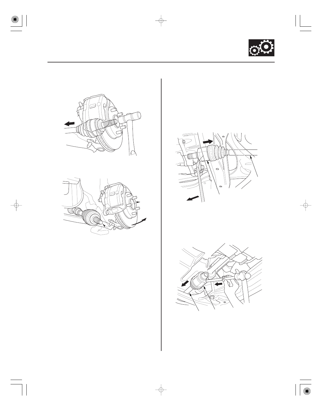
A
B
A
B
6. Separate the driveshaft outboard joint from the
front hub using a plastic hammer.
7. Pull the knuckle outward, and separate the
driveshaft outboard joint from the front hub.
8. Left driveshaft: Pry the inboard joint (A) from the
differential using a prybar. Remove the driveshaft
as an assembly.
NOTE:
• Do not pull on the driveshaft (B), or the inboard
joint may come apart. Pull the inboard joint
straight out to avoid damaging the oil seal.
• Be careful not to damage the oil seal using the
prybar.
9. Right driveshaft: Drive the inboard joint (A) off of
the intermediate shaft using a drift and a hammer.
Remove the driveshaft as an assembly.
NOTE: Do not pull on the driveshaft (B), or the
inboard joint may come apart.
08/08/21 14:51:22 61SNR030_160_0005