Acura CSX. Manual - part 319


  Index      Acura     Acura CSX - P/NO. 61SNR03 - service repair manual 2006-2009 year


Search            


Content   ..  317  318  319  320   ..


Acura CSX. Manual - part 319


*05

*06

*07

14-348

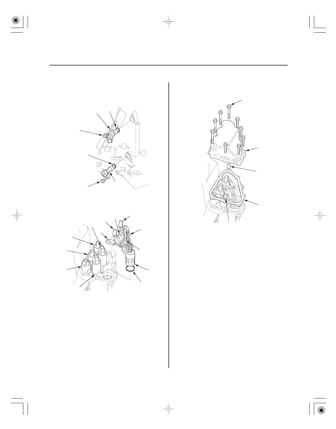
Transmission Housing

B

A

C

C

6 x 1.0 mm
12 N·m
(1.2 kgf·m, 8.7 lbf·ft)

6 x 1.0 mm
12 N·m (1.2 kgf·m, 8.7 lbf·ft)

GRN

ORN

RED

BLU

YEL,
WHT, WHT

G

D

E

B

C

F

A

6 x 1.0 mm
12 N·m
(1.2 kgf·m,
8.7 lbf·ft)

6 x 1.0 mm
12 N·m
(1.2 kgf·m, 8.7 lbf·ft)

C

B

A

B

20. Install the input shaft (mainshaft) speed sensor (A)

and the output shaft (countershaft) speed sensor
(B) with new O-rings (C).

21. Install the shift solenoid wire harness (F) in the

transmission housing with a new O-ring (G).

22. Connect the connectors to the respective valves:

• BLU wire to shift solenoid valve A.
• ORN wire to shift solenoid valve B.
• GRN wire to shift solenoid valve C.
• YEL, WHT, and WHT wire to shift solenoid valve

D.

• RED wire to shift solenoid valve E.

23. Install the shift solenoid valve cover (A) with the

two dowel pins (B) and a new gasket (C).

Replace.

Replace.

Replace.

Replace.

08/08/21 14:52:33 61SNR030_140_0350

*01

SNR9AA1E10410424251KCAT00

Exploded View

14-349

Transmission End Cover

End Cover Installation

A/T CLUTCH PRESSURE
CONTROL SOLENOID
VALVES B and C

TRANSMISSION RANGE
SWITCH COVER

TRANSMISSION
RANGE SWITCH

6 x 1.0 mm

6 x 1.0 mm

28 N·m
(2.9 kgf·m, 21 lbf·ft)

6 x 1.0 mm

TRANSMISSION
END COVER

6 x 1.0 mm
12 Bolts

28 N·m
(2.9 kgf·m, 21 lbf·ft)

CONICAL SPRING
WASHERS

PARK GEAR

STOP SHAFT

PARK
LEVER STOP

LOCK WASHER

14 N·m
(1.4 kgf·m,
10 lbf·ft)

PARK PAWL

PARK PAWL
SPRING

PARK PAWL
SHAFT

PARK LEVER
SPRING

MAINSHAFT
IDLER GEAR

TRANSMISSION
END COVER GASKET

HARNESS CLAMP
BRACKETS

6 x 1.0 mm

ATF JOINT
PIPES

ATF JOINT PIPES

ATF PIPE

6 x 1.0 mm

A/T CLUTCH PRESSURE
CONTROL SOLENOID
VALVE A

Torque Specifications
6 x 1.0 mm: 12 N·m (1.2 kgf·m, 8.7 lbf·ft)

28 N·m
(2.9 kgf·m,
21 lbf·ft)

PARK
LEVER

Replace.

Replace.

Replace.

08/08/21 14:52:34 61SNR030_140_0351

*02

02

03

Special Tools Required

14-350

Transmission End Cover

07GAB-PF50101

B

C

A

D

J

K

G

F

E

A

B

D

6 x 1.0 mm
14 N·m
(1.4 kgf·m,
10 lbf·ft)

C

H

I

Mainshaft holder 07GAB-PF50101

1. Install the mainshaft holder onto the mainshaft.

2. Lubricate the following parts with ATF:

• Splines and threads of the mainshaft.
• Splines of the mainshaft idler gear.
• Old conical spring washer and old locknut.

3. Install the mainshaft idler gear (A), the old conical

spring washer (B), and the old locknut (C) on the
mainshaft (D), and tighten the locknut to 226 N·m
(23.0 kgf·m, 166 lbf·ft).

NOTE:

• Do not tap the idler gear to install.
• Use a torque wrench to tighten the locknut. Do

not use an impact wrench.

4. Install the park lever (A) and the park lever stop (B)

on the selector control shaft (C), then install the
lock bolt with a new lock washer (D). Do not bend
the lock tab of the lock washer until step 18.

5. Install the park pawl shaft (E), the park pawl spring

(F), the park pawl (G), and the stop shaft (H) on the
transmission housing.

6. Lubricate the following parts with ATF:

• Threads and splines of the countershaft.
• Old conical spring washer and old locknut.
• Areas where the park gear contacts the conical

spring washer.

7. Install the park gear (I), the old conical spring

washer (J), and the old locknut (K) on the
countershaft.

8. Lift the park pawl up, and engage it with the park

gear, then tighten the locknut to 226 N·m
(23.0 kgf·m, 166 lbf·ft).

NOTE:

• Do not tap the park gear to install.
• Use a torque wrench to tighten the locknut. Do

not use an impact wrench.

• Countershaft locknut has left-hand threads.

9. Remove the locknuts and the conical spring

washers from the mainshaft and the countershaft.

08/08/21 14:52:35 61SNR030_140_0352

*03

01

*04

02

14-351

A

B

D

C

A

B

6 x 1.0 mm
14 N·m
(1.4 kgf·m, 10 lbf·ft)

C

B

A

6 x 1.0 mm
14 N·m
(1.4 kgf·m,
10 lbf·ft)

A

D

E

B

C

F

10. Lubricate the threads of the shafts, new locknuts

and new conical spring washers with ATF.

11. Install new conical spring washers (A) with facing

stamped mark side up in the direction shown, and
install a new mainshaft locknut (B), a new
countershaft locknut (C), and a new secondary
shaft locknut (D).

12. Tighten the locknuts to 167 N·m (17.0 kgf·m,

123 lbf·ft).

NOTE:

• Be sure to install the conical spring washers in

the direction shown.

• Use a torque wrench to tighten the locknut. Do

not use an impact wrench.

• Countershaft and secondary shaft locknuts have

left-hand threads.

13. Remove the mainshaft holder from the mainshaft.

14. Stake the locknuts into the shafts to a depth (A) of

0.7

1.3 mm (0.03

0.05 in.) using a 3.5 mm punch

(B).

15. Install the control lever (A) on the selector control

shaft (B), and install the bolt with a new lock
washer (C), then bend the lock tab of the lock
washer against the bolt head.

16. Set the park lever in the P position, then check that

the park pawl (A) engages the park gear (B).

17. If the park pawl does not engage fully, check the

distance (C) between the pawl shaft (D) and the
park lever roller pin (E) (see page 14-292).

18. Tighten the lock bolt, and bend the lock tab of the

lock washer (F) against the bolt head.

Replace.

Replace.

Left-hand threads
Replace.

Left-hand threads
Replace.

Replace.

08/08/21 14:52:36 61SNR030_140_0353


Content   ..  317  318  319  320   ..