Acura CSX. Manual - part 312


  Index      Acura     Acura CSX - P/NO. 61SNR03 - service repair manual 2006-2009 year


Search            


Content   ..  310  311  312  313   ..


Acura CSX. Manual - part 312


01

SNR9AA1E10411354171MAAT00

THRUST WASHER, 37 x 58 mm

No.

Part Number

Thickness

Special Tools Required

14-322

14-322

Shafts and Clutches

Secondary Shaft 1st Gear Axial
Clearance Inspection

L
24 x 1.25 mm
29 N·m (3.0 kgf·m, 22 lbf·ft)

K

J

I

G

F

E

D

C

B

A

H

3. If the clearance is out of standard, remove the

37 x 58 mm thrust washer and measure its
thickness.

4. Select and install a new thrust washer, then

recheck.

1

90511-PRP-010

3.900 mm (0.154 in.)

2

90512-PRP-010

3.925 mm (0.155 in.)

3

90513-PRP-010

3.950 mm (0.156 in.)

4

90514-PRP-010

3.975 mm (0.156 in.)

5

90515-PRP-010

4.000 mm (0.157 in.)

6

90516-PRP-010

4.025 mm (0.158 in.)

7

90517-PRP-010

4.050 mm (0.159 in.)

8

90518-PRP-010

4.075 mm (0.160 in.)

9

90519-PRP-010

4.100 mm (0.161 in.)

10

90520-PRP-010

4.125 mm (0.162 in.)

11

90521-PRP-010

4.150 mm (0.163 in.)

12

90522-PRP-010

4.175 mm (0.164 in.)

13

90523-PRP-000

4.200 mm (0.165 in.)

14

90524-PRP-000

4.225 mm (0.166 in.)

15

90525-PRP-000

4.250 mm (0.167 in.)

16

90526-PRP-000

4.275 mm (0.168 in.)

17

90527-PRP-000

4.300 mm (0.169 in.)

18

90528-PRP-000

4.325 mm (0.170 in.)

19

90529-PRP-000

4.350 mm (0.171 in.)

20

90530-PRP-000

4.375 mm (0.172 in.)

5. After replacing the thrust washer, make sure the

clearance is within standard.

6. Disassemble the installed parts from the secondary

shaft.

Attachment, 42 mm I.D. 07QAD-P0A0100

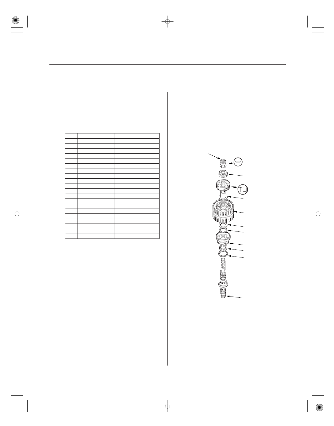
1. Install the thrust needle bearing (A), the needle

bearing (B), 1st gear (C), the thrust needle bearing
(D), the 40 x 51.5 mm thrust washer (E), the 1st/3rd
clutch (F), and the 3rd gear collar (G) on the
secondary shaft (H). Do not install the O-rings
during inspection.

08/08/21 14:51:24 61SNR030_140_0324

02

*01

01

Standard: 0.04

0.12 mm (0.002

0.005 in.)

14-323

07QAD-P0A0100

J

I

A

B

40 x 51.5 mm
THRUST WASHER

A

B

2. Install the idler gear (I), then install the ball bearing

(J) on the idler gear using the 42 mm I.D.
attachment and a press.

3. Install the conical spring washer (K) and the locknut

(L), then tighten the locknut to 29 N·m (3.0 kgf·m,
22 lbf·ft).

4. Turn the secondary shaft assembly upside down,

and set the dial indicator (A) on 1st gear (B).

5. Lift 1st gear (A) up while holding the secondary

shaft, and use the dial indicator (B) to read the 1st
gear axial clearance.

6. Measure the 1st gear axial clearance in at least

three places while moving 1st gear. Use the
average as the actual clearance.

08/08/21 14:51:25 61SNR030_140_0325

01

SNR9AA1E10410434071KDAT00

THRUST WASHER, 40 x 51.5 mm (’06 Model)

No.

Part Number

Thickness

THRUST WASHER, 40 x 51.5 mm (’07-09 Models)

No.

Part Number

Thickness

14-324

14-324

Shafts and Clutches

Idler Gear Shaft Removal and
Installation

D

C

B

A

7. If the clearance is out of standard, remove the

40 x 51.5 mm thrust washer and measure its
thickness.

8. Select and install a new thrust washer, then

recheck.

1

90503-PRP-000

4.80 mm (0.189 in.)

2

90504-PRP-000

4.85 mm (0.191 in.)

3

90505-PRP-000

4.90 mm (0.193 in.)

4

90506-PRP-000

4.95 mm (0.195 in.)

5

90507-PRP-000

5.00 mm (0.197 in.)

6

90508-PRP-000

5.05 mm (0.199 in.)

1

90503-RCT-000

4.80 mm (0.189 in.)

2

90504-RCT-000

4.85 mm (0.191 in.)

3

90505-RCT-000

4.90 mm (0.193 in.)

4

90506-RCT-000

4.95 mm (0.195 in.)

5

90507-RCT-000

5.00 mm (0.197 in.)

6

90508-RCT-000

5.05 mm (0.199 in.)

9. After replacing the thrust washer, make sure the

clearance is within standard.

10. Disassemble the installed parts from the secondary

shaft.

1. Remove the snap ring (A), the cotter retainer (B),

and the cotters (C). Do not distort the snap ring.

2. Remove the idler gear shaft/idler gear assembly (D)

from the transmission housing.

3. Check the snap ring and the cotter retainer for wear

and damage. Replace them if they are worn,
distorted, or damaged.

4. Install the idler gear and the idler gear shaft in the

reverse order of removal.

08/08/21 14:51:25 61SNR030_140_0326


Content   ..  310  311  312  313   ..