Acura CSX. Manual - part 310
*01
03
04
−
−
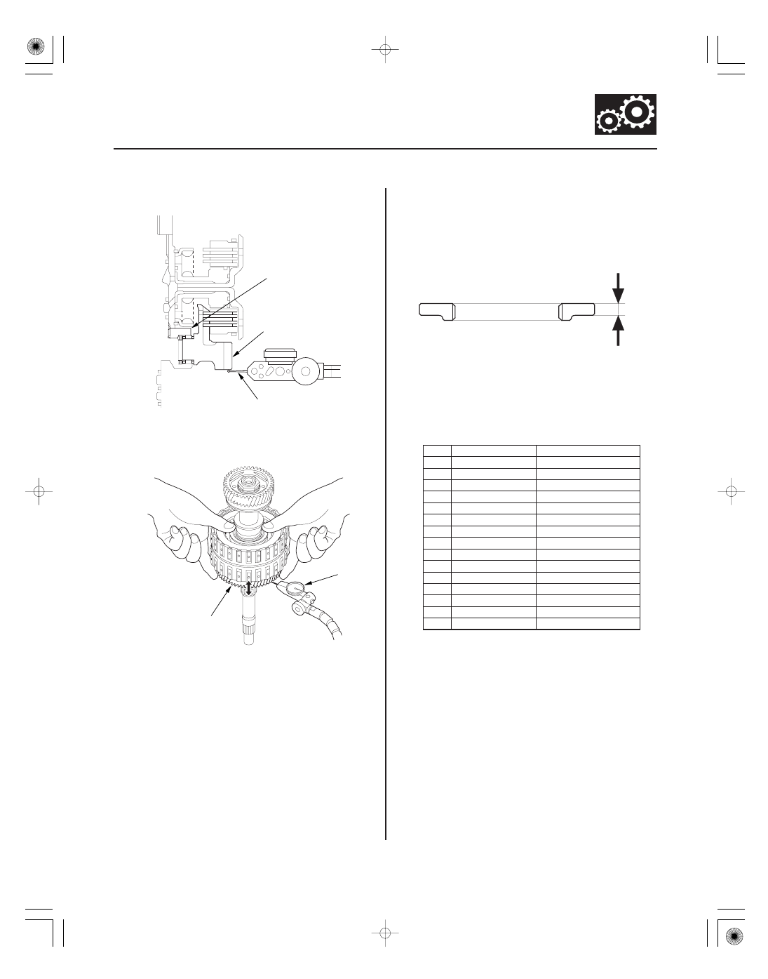
Standard: 0.04
0.10 mm (0.002
0.004 in.)
THRUST WASHER, 41 x 68 mm
No.
Part Number
Thickness
14-315
A
B
41 x 68 mm
THRUST WASHER
A
B
A
5. Set the dial indicator (A) on 5th gear (B).
6. Lift 5th gear (A) up while holding the mainshaft,
and use the dial indicator (B) to read the 5th gear
axial clearance.
7. Measure the 5th gear axial clearance in at least
three places while moving 5th gear. Use the
average as the actual clearance.
8. If the clearance is out of standard, remove the
41 x 68 mm thrust washer and measure its
thickness (A).
9. Select and install a new thrust washer, then
recheck.
1
90414-RCT-000
4.450 mm (0.1752 in.)
2
90415-RCT-000
4.475 mm (0.1762 in.)
3
90416-RCT-000
4.500 mm (0.1772 in.)
4
90417-RCT-000
4.525 mm (0.1781 in.)
5
90418-RCT-000
4.550 mm (0.1791 in.)
6
90419-RCT-000
4.575 mm (0.1801 in.)
7
90420-RCT-000
4.600 mm (0.1811 in.)
8
90421-RCT-000
4.625 mm (0.1821 in.)
9
90422-RCT-000
4.650 mm (0.1831 in.)
10
90423-RCT-000
4.675 mm (0.1841 in.)
11
90424-RCT-000
4.700 mm (0.1850 in.)
12
90425-RCT-000
4.725 mm (0.1860 in.)
13
90426-RCT-000
4.750 mm (0.1870 in.)
14
90427-RCT-000
4.775 mm (0.1880 in.)
15
90428-RCT-000
4.800 mm (0.1890 in.)
10. After replacing the thrust washer, make sure the
clearance is within the standard.
11. Disassemble the installed parts from the mainshaft.
12. Reinstall the bearing in the transmission housing
(see page 14-298).
08/08/21 14:51:20 61SNR030_140_0317