Acura CSX. Manual - part 302


  Index      Acura     Acura CSX - P/NO. 61SNR03 - service repair manual 2006-2009 year


Search            


Content   ..  300  301  302  303   ..


Acura CSX. Manual - part 302


01

SNR9AA1E10436455101FEAT00

01

SNR9AA1E10436455101KBAT01

14-287

14-287

Shift Lock Solenoid Test

Shift Lock Solenoid Replacement

A

A

B

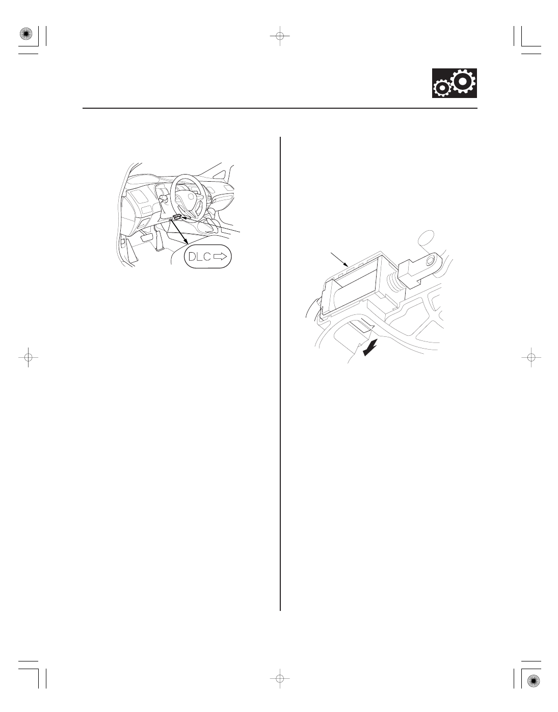
1. Connect the HDS to the DLC (A) located under the

driver’s side of the dashboard.

2. Turn the ignition switch to ON (II). Make sure the

HDS communicates with the PCM. If it does not, go
to the DLC circuit troubleshooting (see page
11-204).

3. Select Shift Lock Solenoid Test in the

Miscellaneous Test Menu, and check that the shift
lock solenoid operates with the HDS.

4. Check that the shift lever can be moved out of P

when Shift Lock Solenoid is ON. Move the shift
lever back in P, and check it locks when Shift Lock
Solenoid is OFF.

5. Check that the shift lock releases when the shift

lock release is pushed, and check that it locks when
the shift lock release is released.

6. If the shift lock solenoid does not work properly, go

to the shift lock system troubleshooting (see page
14-280).

NOTE: Make sure not to get any silicone grease on the
terminal part of the connectors and switches, especially
if you have silicone grease on your hands or gloves.

1. Remove the shift lever assembly (see page 14-254).

2. Remove the shift lock solenoid connector.

3. Release the shift lock solenoid lock (A), then

remove the shift lock solenoid (B).

08/08/21 14:50:09 61SNR030_140_0289

02

01

04

SNR9AA1E10436455151KBAT00

14-288

14-288

A/T Interlock System

Shift Lock Stop, Shift Lock Stop
Cushion Replacement

A

B

C

D

F

E

A

B

A

B

C

D

4. Replace the shift lock solenoid (A), the solenoid

plunger (B), and the plunger spring (C) assembly.

5. Apply silicone grease to the tip (D) of the shift lock

stop (E), and install a new shift lock solenoid
assembly by aligning the joint of the shift lock
solenoid plunger with the tip of the shift lock stop.

6. Route the shift lock solenoid harness in the guide,

and install the connector (F) on the bracket base.

7. Install the shift lever assembly (see page 14-255).

NOTE: Make sure not to get any silicone grease on the
terminal part of the connectors and switches, especially
if you have silicone grease on your hands or gloves.

1. Remove the shift lever assembly (see page 14-254).

2. Release the shift lock solenoid lock (A), then

remove the shift lock solenoid (B).

3. Remove the shift lock release (A) and the release

spring (B).

4. Remove the shift lock stop (C) and the stop cushion

(D), and replace the shift lock stop or the stop
cushion.

5. Install the shift lock stop cushion on the shift lock

stop.

08/08/21 14:50:10 61SNR030_140_0290

01

SNR9AA1E10436445401FEAT00

14-289

14-289

Park Pin Switch Test

6. Apply silicone grease to the pin on the shift lever

bracket base, and install the shift lock stop over the
pin.

7. Install the shift lock release spring and the shift lock

release, apply silicone grease to shift lock release
mounting tip if necessary.

8. Apply silicone grease to the tip of the shift lock stop,

and install the shift lock solenoid assembly by
aligning the joint of the shift lock solenoid plunger
with the tip of the shift lock stop.

9. Route the shift lock solenoid harness in the guide.

10. Install the shift lever assembly (see page 14-255).

1. Remove the center console (see page 20-92).

2. Move the shift lever to P, and check for continuity

between park pin switch/A/T gear position indicator
panel light connector terminals No. 3 and No. 4.
There should be no continuity.

3. Shift out of P, and check for continuity between

connector terminals No. 3 and No. 4.
There should be continuity.

4. If the park pin switch tests OK, install the center

console (see page 20-92).
If the park pin switch fails the test, replace the park
pin switch (see page 14-269).

Terminal side of male terminals

08/08/21 14:50:10 61SNR030_140_0291


Content   ..  300  301  302  303   ..