Acura CSX. Manual - part 248
*01
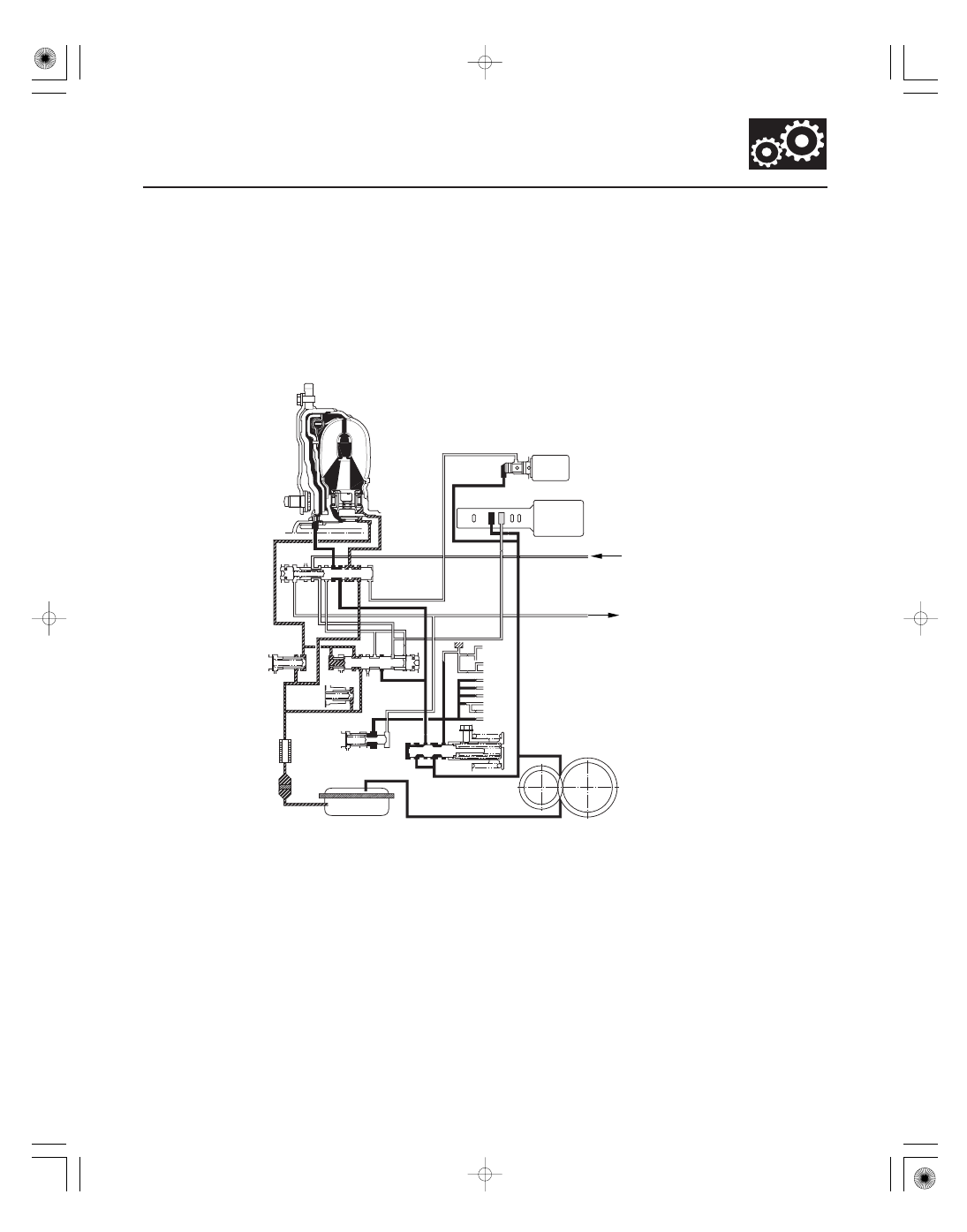
No Lock-up
14-73
TORQUE
CONVERTER
LOCK-UP
SHIFT VALVE
LOCK-UP
CONTROL
VALVE
RELIEF VALVE
ATF
COOLER
COOLER
CHECK
VALVE
TORQUE
CONVERTER
CHECK VALVE
REGULATOR
VALVE
ATF PUMP
A/T CLUTCH PRESSURE CONTROL SOLENOID VALVE A
OFF
SHIFT SOLENOID VALVE E
SHIFT VALVES A and D
MANUAL VALVE
IDLER SHAFT
IDLER GEAR
MAINSHAFT
COUNTERSHAFT
FINAL DRIVE
GEAR
SECONDARY
SHAFT
AX
HX
AX
HX
94
90
91
X
7
55
96
92
93 SE
91
94
55’
97
55
96
90
90 X 93
X
92
90
X
93
95
7
X
X
99
92
95
1
1
SE
1
X
X
1
55
X AX
X
93
The PCM turns shift solenoid valve E OFF, and shift solenoid valve E pressure (SE) is not applied to the lock-up shift
valve. The lock-up shift valve remains to the right uncover the torque converter pressure ports leading to the left side
of the torque converter and releasing pressure from the right side of the torque converter. Torque converter pressure
(92) changes to (94) at the lock-up shift valve, and enters into the left side of the torque converter to disengage the
torque converter clutch. This keeps the torque converter clutch piston keeps away from the torque converter cover and
the torque converter clutch lock-up is OFF.
NOTE: When used, ‘‘left’’ or ‘‘right’’ indicates direction on the hydraulic circuit.
08/08/21 14:39:42 61SNR030_140_0075