Acura CSX. Manual - part 243
01
SNR9AA1E10410800000CAAT04
Hydraulic Controls
Valve Bodies
14-53
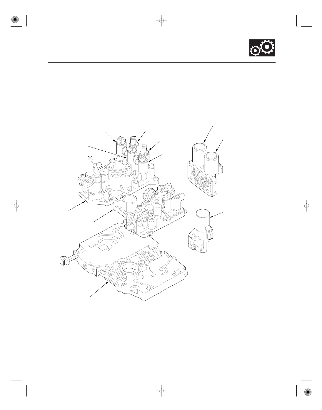
SHIFT SOLENOID
VALVE D
SHIFT SOLENOID
VALVE E
SHIFT SOLENOID
VALVE C
SHIFT SOLENOID
VALVE A
SHIFT SOLENOID
VALVE B
A/T CLUTCH PRESSURE
CONTROL SOLENOID
VALVE B
A/T CLUTCH PRESSURE
CONTROL SOLENOID
VALVE C
A/T CLUTCH PRESSURE
CONTROL SOLENOID
VALVE A
SERVO BODY
REGULATOR
VALVE BODY
MAIN VALVE BODY
The valve body includes the main valve body, the regulator valve body, and the servo body. The ATF pump is driven
by splines on the end of the torque converter which is attached to the engine. Fluid flows through the regulator valve
to maintain specified pressure through the main valve body to the manual valve, directing pressure to the shift valves
and to each of the clutches via the shift solenoid valves. Shift solenoid valves A, B, C, D, and E are bolted on the servo
body. A/T clutch pressure control solenoid valves A, B, and C are mounted on the outside of the transmission housing.
08/08/21 14:38:27 61SNR030_140_0055