Acura CSX. Manual - part 189


  Index      Acura     Acura CSX - P/NO. 61SNR03 - service repair manual 2006-2009 year


Search            


Content   ..  187  188  189  190   ..


Acura CSX. Manual - part 189


04

*02

03

07

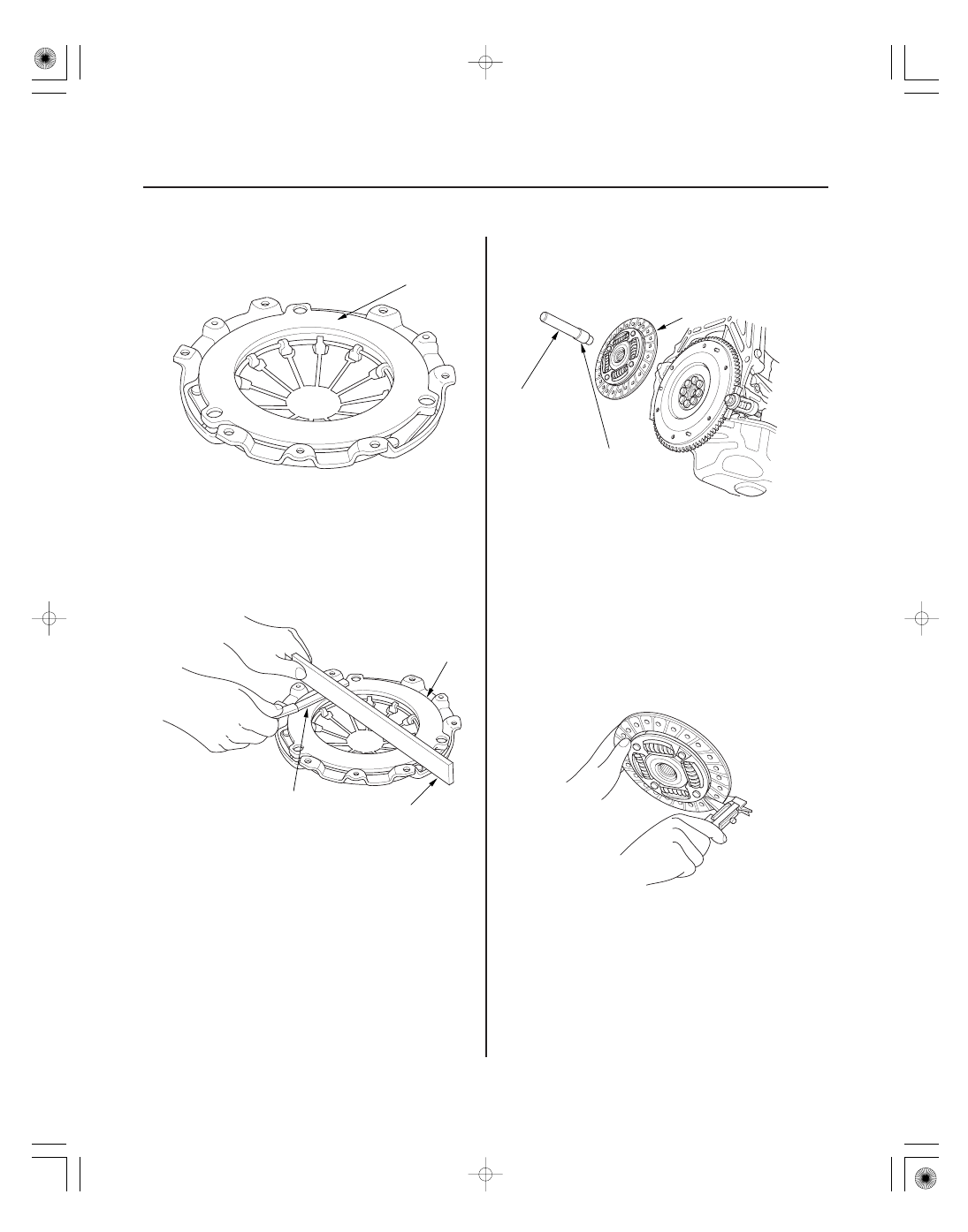
Standard (New): 0.03 mm (0.001 in.) max.
Service Limit:

0.15 mm (0.006 in.)

Clutch Disk Inspection and Removal

Standard (New): 8.3

8.9 mm (0.33

0.35 in.)

Service Limit:

6.0 mm (0.24 in.)

12-20

Clutch

A

B

C

A

C
07936-3710100

B
07ZAF-PR8A100

A

6. Inspect the pressure plate surface (A) for wear,

cracks, and burning.

7. Inspect for warpage using a straight edge (A) and a

feeler gauge (B). Measure across the pressure plate
surface (C). If the most measurement difference is
more than the service limit, replace the pressure
plate.

8. Remove the clutch disc (A), the clutch alignment

shaft (B), and the remover handle (C).

9. Inspect the lining of the clutch disc for signs of

slipping or oil. If the clutch disc looks burnt or is
soaked with oil, replace it and the pressure plate as
a set. If the clutch disc is oil soaked, find and repair
the source of the oil leak.

10. Measure the clutch disc thickness. If the

measurement is less than the service limit, replace
the clutch disc.

08/08/21 14:42:51 61SNR030_120_0022

08

09

*03

Standard (New): 1.65

2.25 mm (0.065

0.089 in.)

Service Limit:

0.7 mm (0.03 in.)

Flywheel Inspection

Standard (New): 0.05 mm (0.002 in.) max.
Service Limit:

0.15 mm (0.006 in.)

Flywheel Replacement

12-21

A

B

B

A

A
07LAB-PV00100

11. Measure the depth of the rivets from the clutch disc

lining surface (A) to the rivets (B) on both sides. If
the measurement is less than the service limit,
replace the clutch disc.

12. Remove the ring gear holder.

13. Inspect the ring gear teeth for wear and damage.

14. Inspect the clutch disc mating surface on the

flywheel for wear, cracks, and burning.

15. Measure the flywheel (A) runout using a dial

indicator (B). Through at least two full turns with
pushing against the flywheel each time you turn it
to take up the crankshaft thrust washer clearance. If
the measurement is not within the standard,
replace the flywheel, and recheck the runout; go to
step 16.

16. Install the ring gear holder (A).

17. Loosen the flywheel mounting bolts in a crisscross

pattern in several steps. Remove the bolts, then
remove the flywheel and the ring gear holder.

08/08/21 14:42:52 61SNR030_120_0023

*04

12

01

*05

Crankshaft Pilot Bushing Inspection

Crankshaft Pilot Bushing Replacement

12-22

Clutch

A
07LAB-PV00100

B
K20Z2 engine model:
12 x 1.0 mm
103 N·m
(10.5 kgf·m, 76 lbf·ft)
K20Z3 engine model:
122 N·m
(12.5 kgf·m, 90 lbf·ft)

B
07936-KC10500

C
07741-0010201

A

C
07746-0010800

B
07749-0010000

2.4

2.6 mm (0.09

0.10 in.)

A

18. Install the flywheel on the crankshaft, and install

the mounting bolts finger-tight.

19. Install the ring gear holder (A), then torque the

flywheel mounting bolts (B) in a crisscross pattern
in several steps.

20. Inspect the crankshaft pilot bushing for wear and

damage.

21. Inspect the inside surface of the crankshaft pilot

bushing with your finger. If the crankshaft pilot
bushing is not smooth, replace it; then go to step
22.

22. Remove the crankshaft pilot bushing (A) using the

bearing remover shaft (B) and the slide hammer (C).

23. Install a new crankshaft pilot bushing (A) into the

crankshaft using the 15 x 135L driver handle (B)
and the 22 x 24 mm bearing driver attachment (C).

08/08/21 14:42:53 61SNR030_120_0024

04

16

*06

Clutch Disc and Pressure Plate Installation

Specified Torque: 25 N·m (2.6 kgf·m, 19 lbf·ft)

12-23

D
07ZAF-PR8A100

E
07936-3710100

(P/N 08798-9002)

C

B

(P/N 08798-9002)

A

B

A

D
07936-3710100

C
07ZAF-PR8A100

B
07LAB-PV00100

A

24. Temporarily install the clutch disc onto the splines

of the transmission mainshaft. Make sure the clutch
disc slides freely on the mainshaft.

25. Apply a light coat of super high temp urea grease

(P/N 08798-9002) to the crankshaft pilot bushing (A).

26. Apply super high temp urea grease (P/N

08798-9002) to the splines (B) of the clutch disc (C),
then install the clutch disc using the clutch
alignment shaft (D) and the remover handle (E).

27. Install the pressure plate (A) and the mounting

bolts (B) finger-tight.

28. Torque the mounting bolts (A) in a crisscross

pattern. Tighten the bolts in several steps to
prevent warping the diaphragm spring.

29. Remove the ring gear holder (B), the clutch

alignment shaft (C), and the remover handle (D).

30. Make sure the diaphragm spring fingers are all the

same height.

31. Do the release bearing inspection, and replace it if

necessary.

32. Install the transmission; 5-speed model (see page

13-14), 6-speed model (see page 13-91).

08/08/21 14:42:54 61SNR030_120_0025


Content   ..  187  188  189  190   ..