Acura CSX. Manual - part 25
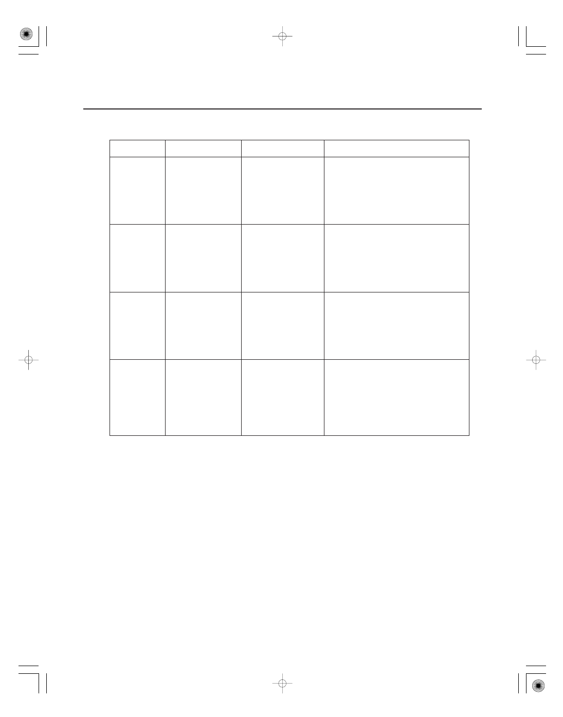
Signal to be
tested
Test condition
Parameter: Desired
result
Possible cause if result is not obtained
4-48
Cruise Control
•
•
•
•
•
•
•
•
•
•
•
•
•
•
•
Set switch
signal
Set/decel button
pressed and released
CRUISE SET SW
should indicate ON
when the set/decel
button is pressed and
OFF when the set/decel
button is released.
Faulty cruise control combination switch
Faulty gauge control module (tach)
An open in the wire between the gauge
control module (tach) and the cruise
control combination switch
A wire shorted to ground between the
gauge control module (tach) and the
cruise control combination switch
Resume
switch signal
Resume/accel button
pressed and released
CRUISE RESUME SW
should indicate ON
when the resume/accel
button is pressed and
OFF when the resume/
accel button is released.
Faulty cruise control combination switch
Faulty gauge control module (tach)
An open in the wire between the gauge
control module (tach) and the cruise
control combination switch
A wire shorted to ground between the
gauge control module (tach) and the
cruise control combination switch
Cancel switch
signal
Cancel button
pressed and released
CRUISE CANCEL SW
should indicate ON
when the cancel button
is pressed and OFF
when the cancel button
is released.
Faulty cruise control combination switch
Faulty gauge control module (tach)
An open in the wire between the gauge
control module (tach) and the cruise
control combination switch
A wire shorted to ground between the
gauge control module (tach) and the
cruise control combination switch
Cruise control
indicator
signal
Start the engine,
press the cruise
control main button
on, and drive the
vehicle to speeds
over 40 km/h
(25 mph). Set and
cancel the cruise
control.
CRUISE INDICATOR
should indicate ON
when the cruise control
is set and OFF when
the cruise control is
canceled.
Faulty ECM/PCM
Cruise control was not set at the test by
other malfunction
Faulty gauge control module (tach)