Lotus Elise / Lotus Exige. Manual - part 53


  Index      Lotus     Lotus Elise / Lotus Exige (engine 1ZZ/2ZZ) - service repair manual 2004 year


Search            


Content   ..  51  52  53  54   ..


Lotus Elise / Lotus Exige. Manual - part 53


Lotus Service Notes                                  Section HG

Page 8

To Remove Upper Steering Column Assembly

WARNING:  On cars so equipped, the driver's airbag is housed in the hub of the steering wheel.
Precautions need to be taken for personal safety when working with airbags and associated
componentry.  Do not attempt to remove the airbag, steering wheel or column without first referring to
section WD.

1.

Disconnect the battery, and remove the column shrouds (see sub-section HG.2).

2.

Disconnect the column lever switches, or release the retaining pawls and slide the switches out of the
carrier.  Disconnect the horn contact pin.  On airbag equipped cars, refer to section WD and unplug the
yellow airbag harness connector.

3.

To disconnect the ignition switch: prise open the terminal cover, and use a small screwdriver to release
the retaining barb located between the white and yellow cables.  Withdraw the connector.

4.

If necessary, remove the steering lock/ignition key barrel: Turn the key to position 'I', depress the spring
pin accessible via a hole in the column switch carrier, and withdraw the lock barrel.

5.

If necessary, remove the ignition switch: First remove the steering lock/ignition key barrel (see above).
Remove the retaining grub screw and withdraw the switch.

6.

If necessary, remove the steering lock assembly: Remove the spline head screw securing the column
switch carrier, and drill or chisel out the two shear head bolts fixing the lock assembly to the column.
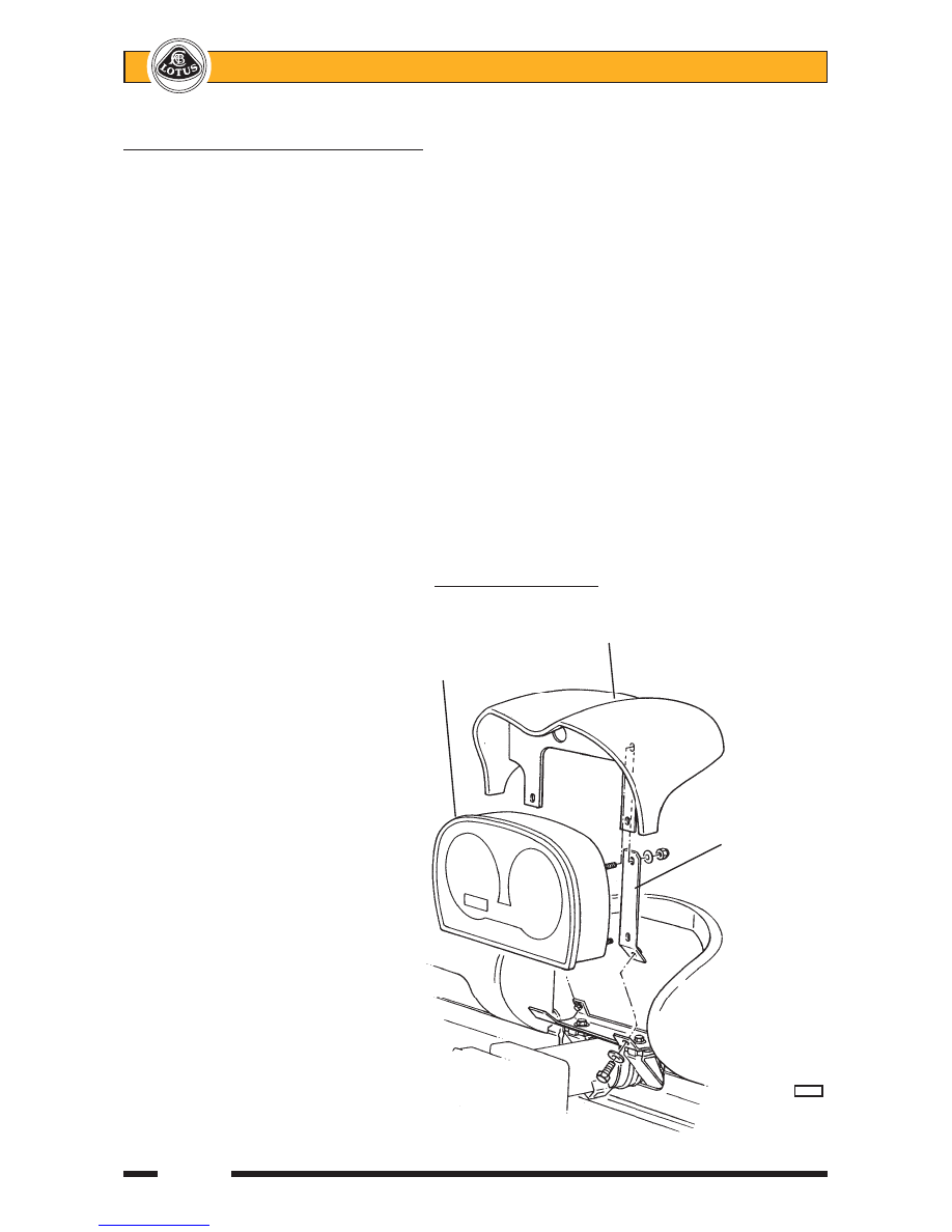
7.

Remove the pinch bolt securing
the upper universal joint to the in-
termediate column.

8.

On non-airbag cars, remove the
two fixings for the instrument pack
mounting brackets, and remove
the instrument pack and cowl as-
sembly after unplugging the sin-
gle harness connector.
On airbag equipped cars, with-
draw the instrument surround and
cowl straight rearwards from the
dash panel to release the spring
clips.  Remove four screws to re-
lease the instrument pack mount-
ing bracket from the dash and
unplug the two harness connec-
tors

9.

Release the two bolts securing the
upper column clamp to the dash
brackets, and remove the switch
pack.

10.

From the access provided by the
removal of the switch pack, re-
lease the upper column single
lower fixing and withdraw the col-
umn assembly from the scuttle
and off the intermediate steering
column.

Non-airbag type shown

Instrument cowl

Instrument
pack

Instrument
& cowl
mounting
bracket

            b259a


Lotus Service Notes                                  Section HG

Page 9

11.

Refit the column in reverse order to removal with the following notes:

-

The groove for the pinch bolt allows assembly of the universal joint to the intermediate column in only one
orientation.  Torque tighten the pinch bolt to 35 Nm.

-

Torque tighten the column lower fixing bolt to 45 Nm

-

Torque tighten the two column upper fixing bolts to 22.5 Nm.

-

If applicable, use new shear bolts to secure the steering lock assembly, and tighten until sheared.

HG.4 - INTERMEDIATE COLUMN

The intermediate steering column consists of a symmetrical splined shaft and two different Hookes type

universal joints.  The lower joint uses an un-indexed 36 spline connection to the steering rack pinion shaft, and
the upper joint accommodates a double flatted boss on the end of the upper column, with a pinch bolt groove
allowing assembly in only one orientation.  The intermediate shaft itself, uses a splined joint at each end and an
indexed pinch bolt groove.

To remove the intermediate column assembly, the upper column must first be removed (see sub-section

HG.3), after which the rack pinion shaft pinch bolt may be removed and the column assembly withdrawn.
Match marking the lower u/j to the pinion shaft will aid steering wheel alignment on re-assembly.  Torque tighten
the pinch bolts to 35 Nm.

HG.5 - TRACK ROD ENDS & RACK GAITERS

Front Wheel Alignment

Alignment is measured either by the angle a wheel makes with the vehicle centre line, or the difference in

dimension between the wheel rim to wheel rim measurement at the front and rear of the wheel at hub centre
height.  The wheels are said to 'toe-in' when the wheel paths converge ahead of the vehicle, and 'toe-out' when
they diverge.  Wheel alignment is designed to vary with both steering angle (Ackermann) and suspension
travel (bump steer) and should be measured only 'straight ahead' at the specified ride height.

Instrument pack

Instrument cowl

Instrument
mounting bracket
fixings (4 off)

Upper column clamp fixings

        b343


Lotus Service Notes                                  Section HG

Page 10

Provision is made for the adjustment of front wheel alignment at the joint between the steering rack track

(tie) rods, and the outer ball joints ('track rod ends').  The required ride height and alignment specification is
detailed in sub-section CI.2.

Note that in order to preserve the required bump steer characteristic and steering symmetry, the effective

length of each track rod must remain equal - adjust each track rod by a similar amount:

-

Hold the track rod end using the flats provided, and slacken the locknut.  Repeat for the opposite side.

-

Turn each track rod a similar amount.  As a guide, turning both track rods by one quarter of a turn will alter
overall toe-out by approx. 2.0 mm.

-

When adjustment is correct, hold each track rod end and tighten the locknuts to 45 Nm (33 lbf.ft).

When slackening or tightening the track rod end locknuts, it is important that the torque reaction is

resisted using the track rod end flats, and that the ball joint itself is not allowed to be stressed.

Track Rod Ends

The track rod ends are sealed for life and maintenance free, but if replacement is required; remove the

ball pin nut and use a ball joint splitter tool to separate the joint from the steering arm.  Unscrew the joint from
the track rod.  On re-assembly, tighten the ball joint to steering arm nut to 30 Nm, and set the front wheel
alignment as detailed in sub-section CI.2.

Steering Rack Gaiters

The convoluted gaiters sealing each end of the steering rack housing to the track rods, should be in-

spected at service intervals and replaced immediately if found to be torn, cracked or otherwise damaged.  The
ingress of dirt or water into the rack housing will cause rapid deterioration of the track rod inner ball joints and
rack and pinion mechanism.

To replace a gaiter, remove the track rod end (see above), release the gaiter clips, and slide the gaiter off

the housing and track rod.  Check for consequent damage or wear and replace the steering gear assembly if
necessary.  Fit the new gaiter into position, and secure with new retaining clips.

HG.6 - RACK & PINION ASSEMBLY REMOVAL/REPLACEMENT

The rack and pinion assembly is mounted inside an extruded chassis box section crossmember at the top

front of the footwell.  Each of the two rack housing mounting plinths uses an M10 (upper) and M8 (lower) fixing
bolt to secure the housing to the vertical rear face of the crossmember.  A steel reinforcement channel is
bonded to the outside of the crossmember, with a riveted height setting plate to define the vertical position of
the housing.  Note that the only approved repairs or adjustments to the steering rack assembly are the replace-
ment of the track rod ends and rack housing gaiters, and the adjustment of the rack pressure pad.

Gaiter

Track rod end flats

Steering arm

Steering track rod flats

Track rod end locknut

       c28a


Lotus Service Notes                                  Section HG

Page 11

To Remove/Replace Steering Assembly
1.

Remove the nut securing each track rod end to the steering arm, and use a ball joint splitter to separate
the joint.

2.

From inside the footwell, match mark the pinion shaft against the u/j yoke to aid steering wheel alignment
on re-assembly, and remove the pinch bolt.

3.

From inside the footwell, remove the two M8 and M10 bolts securing the rack housing.

4.

Draw the housing forwards to disengage the intermediate shaft u/j, and manoeuvre the assembly out of
the chassis crossmember.

5.

On re-assembly, check that the correct rack height setting plate is fitted.  For the standard ride height of
130/130 or 135/135, the '6 notch' plate A111H0017 should be fitted.  Fitment of the wrong plate (identified
by the number of notches in the vertical edges) will result in an incorrect bump steer characteristic and
degraded handling.  The plate is secured to the chassis by a single pop rivet.

6.

Feed the rack assembly into the chassis crossmember and engage the pinion shaft into the lower u/j with
the match marks aligned.  If a new assembly is being fitted, follow the 'Steering Wheel Alignment' proce-
dure in sub-section HG.2.

7.

New fixing bolts for the steering rack housing are precoated with thread locking compound.  If existing
bolts are to be re-used, wire brush the threads before re-applying a suitable thread locking compound and
torque tightening the M8 bolts to 22.5 Nm, and the M10 bolts to 45 Nm.

Steering rack

Steel reinforcement channel (bonded)

assembly

Height setting plate

M10 fixing bolt

M8 fixing bolt

Pop rivet

Chassis
crossmember

          h54


Content   ..  51  52  53  54   ..