Porshe 911 (997). Manual - part 172


  Index      Hummer     Porshe 911 997 series - service repair manual 2004-2008 year


Search            


Content   ..  170  171  172  173   ..


Porshe 911 (997). Manual - part 172


Bracket for clutch power spring

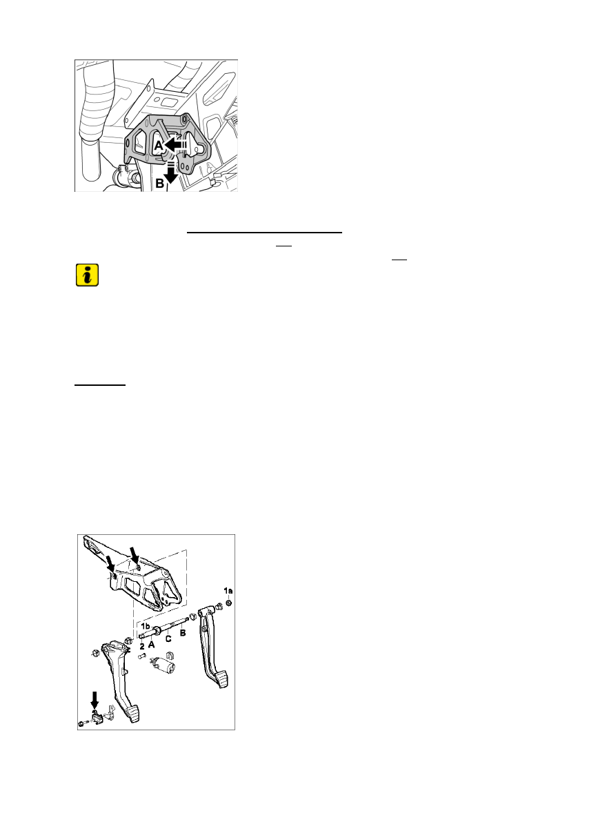
6. Loosen bracket for clutch power spring (support for clutch pedal switch and remove interlock

switch, if necessary) → Bracket for clutch power spring . Carefully move bracket for clutch power
spring approximately 2-4 mm to the left -A- . Carefully turn bracket for clutch power spring
clockwise on the pedal bearing axle approximately 10-15 degrees -B-
 .

Note

When removing the bracket for the clutch power spring, carefully guide the master cylinder valve pushrod
past at the clutch pedal.

7. Pull out bracket for clutch power spring to the left and take out the clutch

pedal.

Installing

Diagnostic system: reading out fault memory and activating systems

Removing

845

Grease specification

Note

Grease bracket in area of pedal bearing axle -arrows- with Renocal (Glissando VW 745). Part number
000.043.206.21 (10 g tube).
Please note: By contrast with previous models, do not grease the pedal bearing axle in the area of the clutch
pedal -A- (due to plastic-coated bearing sleeves).
Also grease the clutch pedal switch system (interlock switch) -arrow-
 with Renocal (Glissando VW 745)
(part number 000.043.206.21).
Observe correct tightening torques.
Use new lock for bolts.
When installing the bracket for clutch power spring, insert the valve pushrod for the master cylinder carefully
into the specified position in the clutch pedal.

1. Insert bracket for clutch power spring with clutch pedal.

Clutch pedal switch support

2. Position support for clutch pedal switch (and interlock switch, if necessary) in the correct position.

Observe the auxiliary bar! -arrow- The auxiliary bar must be fitted in the correct position in the groove.

3. Install clutch power spring. Observe the installation position of the bolt for the clutch power spring

(hexagon!). After installation, remove the clutch power spring cotter pin.

Note

Insert pin. Screw in the fastening screws slightly so that the master cylinder can still be moved. Have the
clutch pedal not actuated at the limit stop. Press the clutch master cylinder in the direction of travel and
tighten (make sure the return bore in the clutch master cylinder is not blocked!).

4. Mount the clutch master cylinder.

Adjustment for clutch pedal switch (interlock switch)

Diagnostic system: reading out fault memory and activating systems

Installing

846

Note

If the clutch pedal switch adjustment (interlock switch) has been changed, the adjustment must be checked or
adjusted. The switch must switch when the clutch pedal is actuated approx. 1-2 mm before the limit stop of
the clutch master cylinder.

5. Check adjustment for clutch pedal switch (and interlock switch, if necessary). → Adjustment for clutch

pedal switch (interlock switch) Plug in connector.

6. Install device support, vehicle electrical system control unit and relay carrier.

7. Install the side trim panel for the fusebox and cover in the left driver's

footwell.

Subsequent work

Installing trim panel (lower part of dashboard)

1. Screw in the fastening screws -1- and swivel the trim panel under the dashboard on the driver's side -2-

upwards -arrow A- → 701919 Removing and installing trim under instrument panel.

2. Install covers for centre console → 681419 Removing and installing centre console cover.

997110, 997111, 997120, 997121, 997310, 997311, 997320, 997321, 997410, 997411, 997430, 997431,
997610, 997611, 997620, 997621

WARNUNG

Diagnostic system: reading out fault memory and activating systems

847

Gefahr des Verlusts der Text-Bild-Zuordnung beim Ausdruck.

Aus technischen Gründen kann derzeit nicht ausgeschlossen werden, dass trotz
einwandfreier Darstellung auf dem Bildschirm beim Ausdruck der
Zusammenhang von Text und zugehörigem Bild verloren geht.

• 

Wird der Fehler nicht bemerkt, besteht die Gefahr, daß Arbeiten nicht korrekt
durchgeführt werden und es dadurch zu Personen- und Sachschäden kommt.

• 

→ Vergleichen Sie deshalb nach dem Druckvorgang unbedingt die Ausdrucke mit der
Bildschirmdarstellung. Korrigieren Sie die Ausdrucke im Fehlerfall so, daß der Inhalt der
Bildschirmdarstellung zutreffend wiedergegeben wird.

WARNING

Danger of losing text-figure correspondence when printing out.

For technical reasons, it can currently not be ruled out that the correspondence
between text and associated figure can be lost when it is printed out, even though
the display on the screen is correct.

• 

If the fault is not noticed, there is the danger that work will not be performed
correctly which can cause injury and damage.

• 

→ Therefore, always compare printouts with the screen display after printing them out. Correct
the printouts if they are faulty so that the content of the screen display matches that on the
printouts.

AVERTISSEMENT

Risque de perte de la correspondance texte-illustration lors de l'impression papier.

Pour des raisons techniques, il ne peut pas être exclu à l'heure actuelle que, même
en cas d'affichage correct à l'écran, la correspondance entre le texte et l'illustration
puisse être erronée sur l'impression papier.

• 

Si l'erreur passe inaperçue, on court le risque d'exécuter certaines opérations de
manière incorrecte pouvant conduire à des dommages corporels et matériels.

• 

→ Comparez impérativement pour cette raison les impressions papier avec l'affichage à l'écran.
Corrigez-les en cas d'erreur de manière à reproduire correctement l'affichage à l'écran.

ATTENZIONE

Pericolo di perdita dell'abbinamento testo-immagine nella stampa.

Per motivi tecnici non è escluso che, nonostante la rappresentazione sullo schermo
risulti perfetta, durante la stampa venga persa la corrispondenza fra testo e
relativa immagine.

• 

Se tale difetto non viene rilevato vi è il pericolo che i lavori non siano eseguiti
correttamente; ciò può avere come conseguenza lesioni e danneggiamenti.

• 

Diagnostic system: reading out fault memory and activating systems

Subsequent work

848


Content   ..  170  171  172  173   ..