Kenworth T680. Manual - part 6


  Index      Kenworth     Kenworth T680 - service repair manual 2014 year


Search            


Content   ..  4  5  6  7   ..


Kenworth T680. Manual - part 6


7.2. 

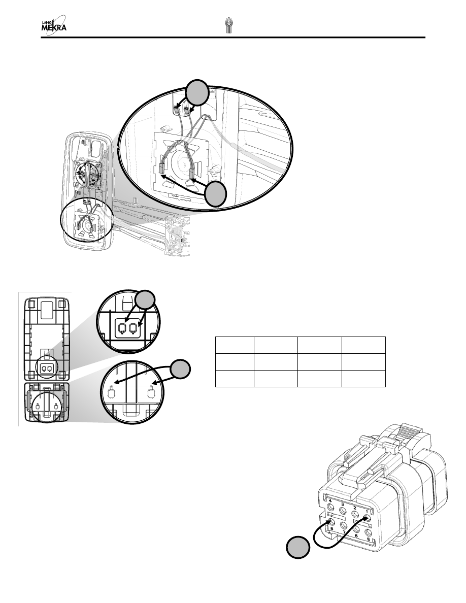
VOLTAGE AT HEATER TERMINALS 

Check for voltage between the connectors on both sets of connectors when the heater is switched on. 


7.3. 

HEATER FOIL CHECKING 


7.4. 

TRUCK CONNECTOR CHECKING 

When the heater is switched on 

 measure voltage between 

cavities “1” and “8” 

If no voltage is recorded then problem is inside the cab. 


Type 

Min 

Nom 

Max 

Main 

3.8 

Ω 

4.4 

Ω 

5.0 

Ω 

Convex 

6.2 

Ω 

7.1  

Ω 

8 Ω 

Measure the resistance of the heater foil in question. 
Compare your measurements with the table below. 


Ω 


8.1. 

ANALYSIS 


Remote Mirror will not move  

Is the Actuator present?        

(To identify it see 8.2 )  

Is Voltage present at actuator 

connector when switch is 

operated? See 8.3 

Is Voltage present at truck 

connector when switch is 

operated? See 8.4 


Wire Harness continuity ok? 

See 6.4.1 

Is Actuator working when 

voltage is applied directly to 

the terminals? See 8.3 

Replace control cable 

Kit #4 or 5 - See 

Error! 

eference source not found.


and 6.1 

Replace mirror with remote 

control mirror (if remote power 

mirrors are desired) 

Check connection at terminals.  

Make sure connection is secure.  


Yes 

Yes 

Yes 

No 

No 

No 

No 

Cab-internal problem 

See truck fault finding 

Work instructions 

Replace Actuator 

Kit #1 - See 4 

Yes 

No 

Yes 

Check connection at terminals.  

Make sure connection is secure.  

Remove the mirror from the truck. 

See 1


Remove housing and unplug Actuator connector. 

See 3 and 4


Remove the main glass

. See 2.2


ACTUATOR VOLTAGE CHECKING 

With a voltmeter check if there is 12V when operating the mirror from the truck cab. 

 

When operating up and down, check between 

 and 


 

When operating Left and Right check between 

 and 


8.3. 

ACTUATOR CHECKING 

Apply 12V between 

 and 

: the actuator should work up or down


Apply 12V between 

 and 

: the actuator should work left or right 


8.4. 

TRUCK CONNECTOR CHECKING 

With a voltmeter check if there is 12V 

while operating

 the mirror from the truck cab; 

 

Up and down - 

check between cavity “2” and “4”  

 

Left and Right - 

check between cavity “2” and “3” 


If no voltage is recorded then problem is inside the cab. 


Left Hand 

Right Hand 

White 

Grey 

Grey 

White 

White 

Yellow 

Yellow 

White 

Direction 

Motor 

   Up 


   Down 


   Left 


   Right 


Left/Right 

Up/Down 


ITEM 

KENWORTH P# 

LMNA P# 

DESCRIPTION 

R59-6092-220000 

594810001-PDC 

MIRROR SYS,LH,RMT,HTD 

R59-6093-220000 

594810002-PDC 

MIRROR SYS,RH,RMT,HTD 

R59-6092-221000 

594810003-PDC 

MIRROR SYS,LH,RMT,HTD,CB 

R59-6093-221000 

594810004-PDC 

MIRROR SYS,RH,RMT,HTD,CB 

R59-6089-102 

594120002-PDC 

LOOKDOWN MIRROR ASSEMBLY 

614810003 

614810003-PDC 

KIT - BEZEL LH 

614810004 

614810004-PDC 

KIT - BEZEL RH 

R22-6123-100 

134810003-PDC 

HOUSING,LH,PRIMED WITH CLIPS 


10 

R22-6124-100 

134810004-PDC 

HOUSING,RH,PRIMED WITH CLIPS 

11 


12 

154810011 

154810011-PDC 

CARRIER ASSY,MAIN,NH,HTD 

13 

154810012 

154810012-PDC 

CARRIER ASSY,CONVEX,NH,HTD 

14 

084803997 

084803997-PDC 

KIT - ACTUATOR 

15 

094800013 

094800013-PDC 

KIT - CONTROL CABLE,LH,RMT,HTD,OAT 

16 

094800014 

094800014-PDC 

KIT - CONTROL CABLE,RH,RMT,HTD 

17 

614800003 

614800003-PDC 

KIT - OAT REPLACEMENT 

18 

614800004 

614800004-PDC 

KIT - CONNECTOR 

19 

614810008 

614810008-PDC 

CB CABLE 

20 

614810005 

614810005-PDC 

KIT – CB CABLE WITH ACCESSORIES 

21 

204810008 

204810008-PDC 

ELECTRICAL CONNECTOR BRACKET 

22 

204810015 

204810015-PDC 

KIT – CB PLATE LH 

23 

204810016 

204810016-PDC 

KIT – CB PLATE RH 

24 

204810023 

204810023-PDC 

KIT - BLANK PLATE LH 

25 

204810024 

204810024-PDC 

KIT - BLANK PLATE RH 

26 

114810002 

114810002-PDC 

KIT – CLIPS 


Content   ..  4  5  6  7   ..