Engine International VT365. Manual - part 10


  Index      International     Engine International VT365 - service repair manual 2006 year


Search            


Content   ..  8  9  10  11   ..


Engine International VT365. Manual - part 10


ENGINE SYSTEMS

37

Cooling System

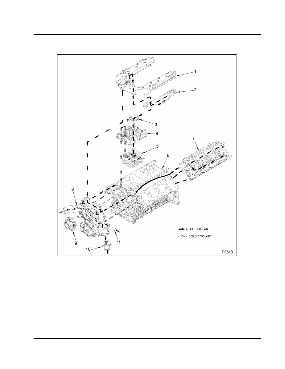
Figure 31 Engine cooling system components

1.

Intake manifold

2.

EGR cooler

3.

Coolant outlet cap

4.

Oil cooler cover

5.

Oil cooler (not serviced
separately)

6.

Crankcase

7.

Cylinder head

8.

Front cover housing

9.

Water pump

10. Thermostat assembly

11. Coolant deaeration fitting (to

deaeration tank)

38

ENGINE SYSTEMS

The cooling system keeps the engine within a
designated temperature range.

The centrifugal water pump (hub and impeller) is
mounted in the pump housing of the front cover. The
water pump has a built in reservoir to catch small
amounts of coolant that may seep past the seal.

CAUTION: The water pump impeller may be
damaged if dropped or hit by a hard object.

Front cover housing flow

The water pump draws coolant from the radiator
through inlet of the front cover housing. Coolant flows
from the water pump through three passages in the
front cover.

Two passages (left and right) direct coolant into
the crankcase (front to rear) to cool the cylinder
walls and the cylinder heads.

The third passage directs coolant through a
passage in the crankcase to the oil cooler cover.

NOTE: If an oil cooler seal is damaged, weep holes in
the oil filter base allow coolant to seep from the cooler
cover.

Coolant returns to the water pump through three
passages in the front cover.

Two passages (left and right) from the crankcase
direct coolant to the front cover.

A third passage directs coolant from the intake
manifold to the front cover.

Return coolant is directed to the thermostat in the front
cover.

If the thermostat is open, coolant flows to the
radiator.

If the thermostat is closed, coolant returns to the

water pump through a bypass passage in the front
cover, because the radiator outlet is blocked.

As the engine reaches operating temperatures, the
thermostat opens and directs coolant to the radiator.
This also restricts the bypass opening.

Crankcase and cylinder head flow

Coolant flows through passages in the front cover
to the left and right sides of the crankcase. Coolant
flows through the front of both sides of the crankcase,
evenly distributing coolant around the cylinders, and
exits the rear of the crankcase flowing up to the
cylinder heads.

Coolant flows from the rear of the cylinder heads to
the front of the cylinder heads, exits down a passage
in the crankcase, and returns to the front cover.

Oil cooler and EGR cooler flow

The front cover directs coolant to a passage in the
crankcase. Coolant flows from the crankcase to the
front of the oil cooler cover. The oil cooler and the oil
filter base direct coolant to the front of the oil cooler.

Coolant flows through the oil cooler from the front to
rear and exits through the EGR cooler supply port.

Coolant flows from the rear of the EGR cooler to the
front returning to the front cover though a passage in
the intake manifold.

The deaeration port is on top of the intake
manifold.

For engines equipped with an air compressor
the deaeration point is at the air compressor and
intake manifold.

NOTE: Earlier engines have a single line from the
air compressor to the deaeration tank. Later engines
have two lines. One from the intake and one from the
air compressor that intersect one line to the deaeration
tank.

ENGINE SYSTEMS

39

Electronic Control System

Electronic Control System Components

Figure 32

Operation and function

The Electronic Control Module (ECM) monitors and
controls engine performance to ensure maximum
performance and adherence to emissions standards.
The ECM has four primary functions:

Provides Reference Voltage (V

REF

)

Conditions input signals

Processes and stores control strategies

Controls actuators

1. Reference voltage (V

REF

)

The ECM supplies a 5 volt V

REF

signal to input sensors

in the electronic control system.

By comparing

the 5 volt V

REF

signal sent to the sensors with their

respective returned signals, the ECM determines
pressures, positions, and other variables important to
engine and vehicle functions.

The ECM supplies two independent circuits for V

REF

:

V

REF

A supplies 5 volts to engine sensors

V

REF

B supplies 5 volts to vehicle sensors

2. Signal conditioner

The signal conditioner in the internal microprocessor
converts analog signals to digital signals, squares up
sine wave signals, or amplifies low intensity signals to
a level that the ECM microprocessor can process.

40

ENGINE SYSTEMS

3. Microprocessor

The

ECM

microprocessor

stores

operating

instructions (control strategies) and value tables
(calibration parameters). The ECM compares stored
instructions and values with conditioned input values
to determine the correct operating strategy for all
engine operations.

Continuous

calculations

in

the

ECM

occur

at

two different levels or speeds:

Foreground and

Background.

Foreground calculations are much faster than
background calculations and are normally more
critical for engine operation. Engine speed control
is an example.

Background calculations are normally variables
that change

at a

slower

rates.

Engine

temperature is an example.

Diagnostic Trouble Codes (DTCs) are generated by
the microprocessor, if inputs or conditions do not
comply with expected values.

Diagnostic strategies are also programmed into the
ECM. Some strategies monitor inputs continuously
and command the necessary outputs to achieve the
correct performance of the engine.

Microprocessor memory

The

ECM

microprocessor

includes

Read

Only

Memory (ROM) and Random Access Memory (RAM).

ROM

ROM stores permanent information for calibration
tables and operating strategies. Permanently stored
information cannot be changed or lost by turning
the ignition switch to OFF or when ECM power is
interrupted. ROM includes the following:

Vehicle configuration, modes of operation, and
options

Engine Family Rating Code (EFRC)

Engine warning and protection modes

RAM

RAM

stores

temporary

information

for

current

conditions.

Temporary information in RAM is lost

when the ignition switch is turned OFF or when ECM

power is interrupted. RAM information includes the
following:

Engine temperature

Engine rpm

Accelerator pedal position

4. Actuator control

The ECM controls the actuators by applying a low
level signal (low side driver) or a high level signal
(high side driver). When switched on, these drivers
complete a ground or power circuit to an actuator.

Actuators are controlled in three ways (determined by
the kind of actuator):

A duty cycle (percent time on/off)

A controlled pulse width

Switched on or off

ECM Control of Engine Operation

The ECM controls engine operation with the following:

VGT control valve

EGR valve

IPR valve

Glow plug relay

VGT control valve

The VGT control valve is an actuator mounted on
the top right side of the VGT. The VGT control valve,
a variable position valve, controls vane position in
the turbine housing. Vane position is controlled by
a switching voltage source in the ECM. The ground
circuit is supplied directly from battery ground at all
times.

Actuator control is achieved by setting a pulse width
modulated signal in response to engine speed,
desired fuel quantity, boost or exhaust back pressure
and altitude.

Exhaust Gas Recirculation (EGR) valve

The EGR valve controls the flow of exhaust gases into
the intake manifold.

The EGR drive module controls the DC motor in the
EGR valve.


Content   ..  8  9  10  11   ..