Engine International VT365. Manual - part 11
ENGINE SYSTEMS
41
The EGR drive module receives the desired EGR
valve position from the ECM across the CAN 2
datalink to activate the EGR valve for exhaust gas
recirculation.
The EGR drive module provides feedback to the ECM
on the valve position. When an EGR control error is
detected, the EGR drive module sends a message to
the ECM and a DTC is set.
Injection Pressure Regulator (IPR)
The IPR valve controls pressure in the Injection
Control Pressure (ICP) system. The IPR valve is a
variable position valve controlled by the ECM. This
regulated pressure actuates the fuel injectors. The
valve position is controlled by switching the ground
circuit in the ECM. The voltage source is supplied by
the ignition switch.
Glow plug relay
The ECM activates the glow plug relay. The relay
delivers V
BAT
to the glow plugs for up to 120 seconds,
depending on ambient temperature and altitude. The
ground circuit is supplied directly from the battery
ground at all times.
The relay is controlled by
switching on a voltage source from the ECM.
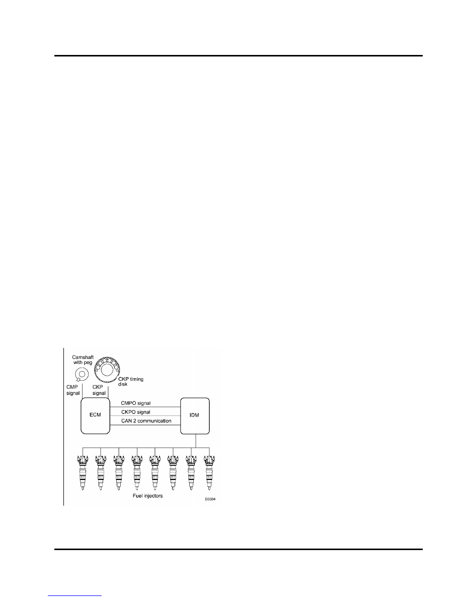
Injection Drive Module (IDM)
Figure 33 Injection Drive Module (IDM)
The IDM has three functions:
•
Electronic distributor for injectors
•
Power source for injectors
•
IDM and injector diagnostics
Electronic distributor for injectors
The IDM distributes current to the injectors. The IDM
controls fueling to the engine by sending high voltage
pulses to the OPEN and CLOSE coils of the injector.
The IDM uses information from the ECM to determine
the timing and quantity of fuel for each injector.
The ECM uses CMP and CKP input signals to
calculate engine speed and position.
The ECM
conditions both input signals and supplies the IDM
with CMP and CKP output signals. The IDM uses
CMP and CKP output signals to determine the correct
sequence for injector firing.
The ECM sends information (fuel volume, EOT, and
ICP) through the CAN 2 link to the IDM; the IDM uses
this information to calculate the injection cycle.
Injector Power Source
The IDM creates a constant 48 volt (DC) supply to
all injectors by making and breaking a 12 volt source
across a coil in the IDM. The 48 volts created by the
collapsed field is stored in capacitors until used by the
injectors.
The IDM controls when the injector is turned on and
how long the injector is active. The IDM first energizes
the OPEN coil, then the CLOSE coil. The low side
driver supplies a return circuit to the IDM for each
injector coil (open and close). The high side driver
controls the power supply to the injector. During each
injection event, the low and high side drivers are
switched on and off for each coil.
IDM and injector diagnostics
The IDM determines if an injector is drawing enough
current. The IDM sends a fault to the ECM, indicating
potential problems in the wiring harness or injector,
and the ECM will set a DTC. The IDM also does self
diagnostic checks and sets a DTC to indicate failure
of the IDM.
On demand tests can be done using the Electronic
Service Tool (EST). The EST sends a request to the
ECM, the ECM sends a request to the IDM to do a