Engine International VT365. Manual - part 5
ENGINE SYSTEMS
17
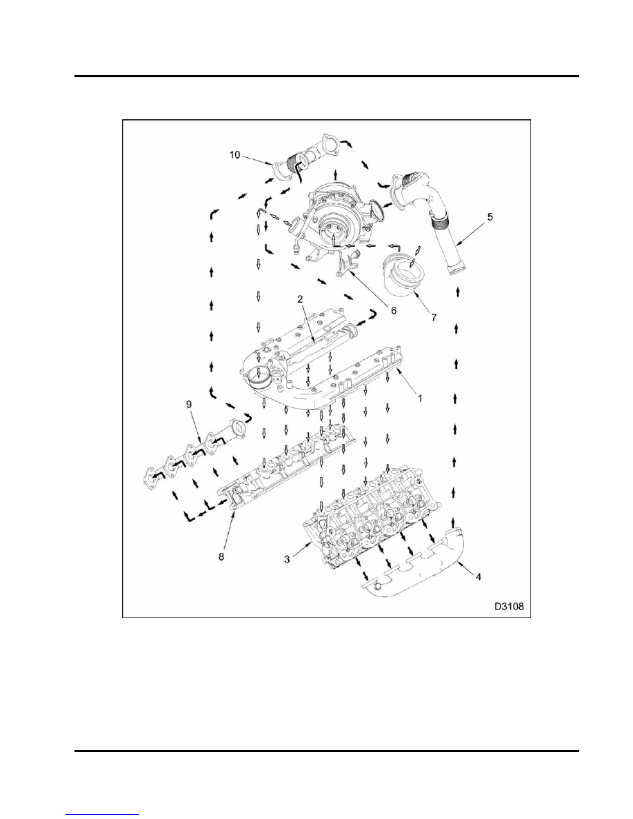
Air Management System (AMS)
Figure 11 Air Management System (AMS)
1.
Intake manifold
2.
EGR cooler
3.
Left cylinder head
4.
Left exhaust manifold
5.
Shielded tube exhaust assembly
6.
VGT with mounting bracket
7.
Air inlet duct
8.
Right cylinder head
9.
Right exhaust manifold
10. Exhaust tube assembly, right